


Install the Kit
3A1324B 5
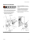
Install the Power CAN Cables
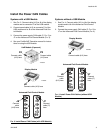
Systems with a USB Module
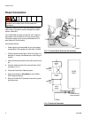
1. See FIG. 3. Connect cable (413) to J6 of the display
module and to connector P3 of the USB module.
2. Connect saved cable (412) to connector P4 of the
USB module and to J8 of the Advanced Fluid Con-
trol Module.
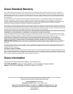
3. Connect the power supply CAN cable (C, F
IG. 2) to
J7 on the Advanced Fluid Control Module (F
IG. 3).
4. See your ProMix 2KE Operation manual for instruc-
tions on using the USB module.
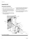
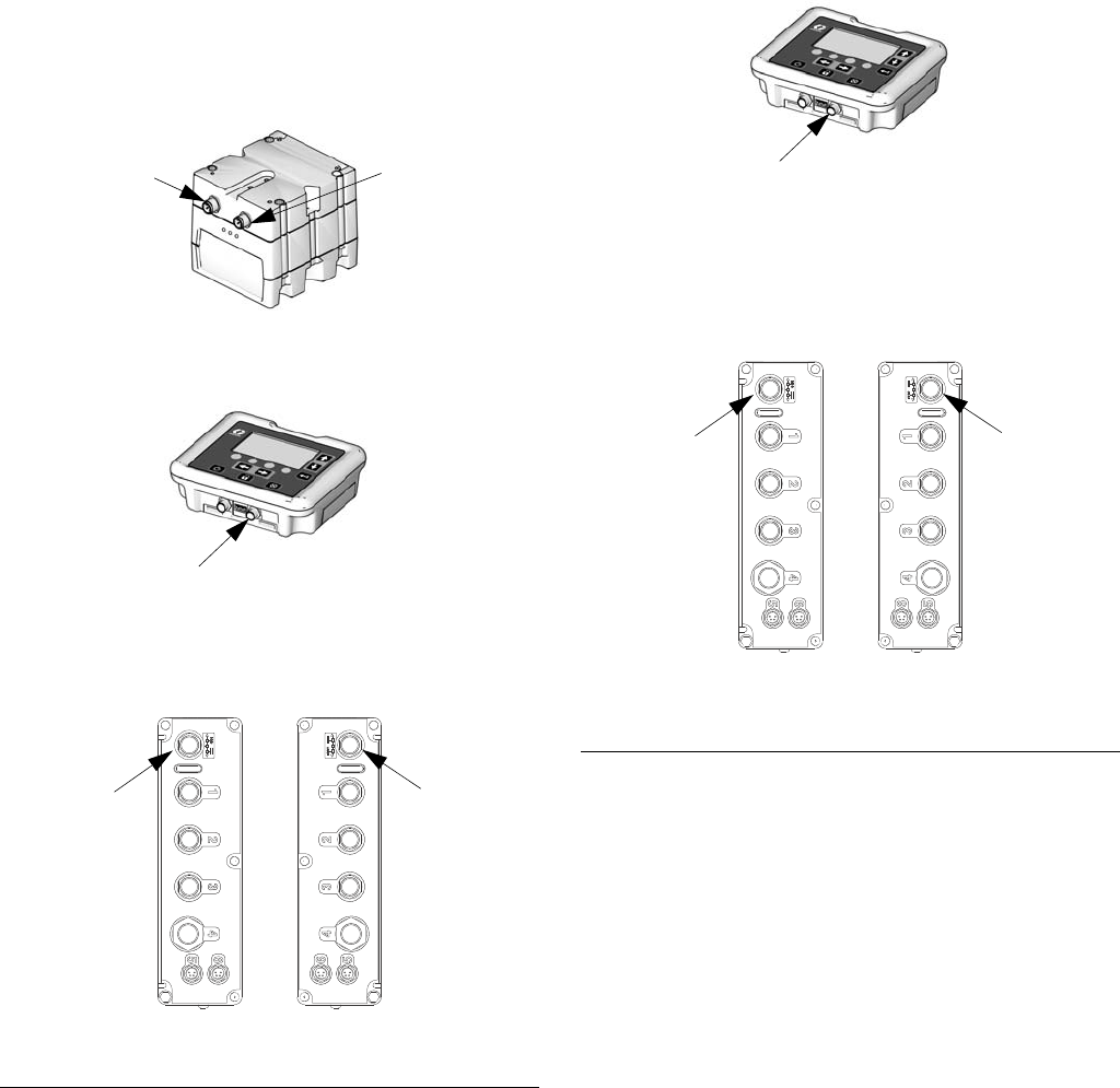
Systems without a USB Module
1. See FIG. 4. Connect cable (413) to J6 of the display
module and to J8 of the Advanced Fluid Control
Module.
2. Connect the power supply CAN cable (C, F
IG. 2) to
J7 on the Advanced Fluid Control Module (F
IG. 4).
FIG. 3. Install Power CAN Cables (with USB Module)
TI16602a
U
S
B Module (if present)
Advanced Fluid Control Module
TI16604a
J7
Connect
cable (C)
here
P3
Connect cable
(413) here
J6
Connect cable (413) here
P4
Connect cable
(412) here
TI16579a
TI16580a
Display Module
J8
Connect
cable
(412) here
FIG. 4. Install Power CAN Cables (without USB
Module)
TI16602a
Advanced Fluid Control Module
TI16604a
J7
Connect
cable (C)
here
J6
Connect cable (413) here
TI16579a
Display Module
J8
Connect
cable
(413) here