


Page 3
14540
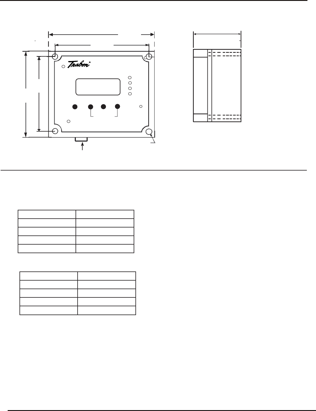
LC-1000 Lube System Controller
76.2
(3.00)
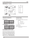
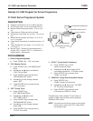
DIMENSIONS mm / (Inches)
114.3
(4.50)
127.0
(5.00)
114.3
(4.50)
4.8 (.19)
POWER
LUBE
FAULT
CYCLE
LUBE SYSTEM
CONTROLLER
TIME COUNTS REMAINING
MANUAL RUN
PRGM
ENTER
MODEL LC-1000
MANUAL
RUN BUTTON
127.0
(5.00)
ORDERING INFORMATION
PROGRAMMING INSTRUCTIONS
The LC-1000 Controller has icons in the display to indi-
cate if the unit is in a lube ON cycle or OFF cycle and to
show the timing mode. They are also used to indicate
which counter is being adjusted when programming new
parameters. The LCD four digit display is used to show
the remaining time left in either an ON or OFF cycle, as
indicated by the icons. Timing can be done in seconds,
minutes, hours or counts. A fl ashing LCD character
indicates that the timer is in the Programming mode.
VOLTAGE PART NUMBER
12 VDC 163-400-050
24 VDC 163-400-051
115 VAC, 50/60 Hz 163-400-052
230 VAC 50/60 Hz 163-400-053
VOLTAGE PART NUMBER
12 VDC 572-144-644
24 VDC 572-144-645
115 VAC, 50/60 Hz 572-144-646
230 VAC 50/60 Hz 572-144-647
Replacement Board
LC-1000 Controller
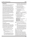
PUSH BUTTONS:
There are four mini push buttons;
PRGM - Initiate Program mode, or alternate between
settings for:
ON (Monitor Time)
OFF (Pause Time)
CYCLE (Switch Transitions)
PUMP (Pulsed On Time)
S - Increase digit
X - Next digit select
ENTER - Enter (save) new setting and advance to
next program step.
S
X