


10 308178
Service
6. Place the o-ring (15*) on the bolt (14). Install the
lower diaphragm plate (12), with the flat side facing
down.
7. Install the diaphragm (13**), making certain that
the side marked AIR SIDE is facing up on the bolt.
On Models 224892 and 224894 only, install the
PTFE diaphragm (21**) first, then the backup
diaphragm (13**).
8. Install the upper diaphragm plate (32*) with the flat
side facing up. Apply thread sealant to the bolt
(14). Hold the bolt steady with a wrench, and
screw the nut (31) onto the bolt (14). Torque to 5 to
7 ft-lb (7 to 10 N-m).
9. Wrap the shaft (11) with a rag to protect it, and use
locking pliers to screw the shaft onto the bolt (14).
Torque to 10 to 15 in-lb (1.1 to 1.7 N-m).
10. Lubricate the inner diameter of the housing (8) with
lithium-based grease. Slide the shaft and
diaphragm assembly into the housing (8). Place
the cover (7) on the housing (8).
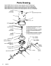
11. Position the clamp (6) around the housing (8) and
cover (7). Apply thread lubricant to the threads of
the v-clamp, secure with the nuts, and torque to 6
to 10 ft-lb (8 to 14 N.m). See the Parts Drawing
on page 12.
Servicing the Fluid Inlet and Outlet
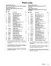
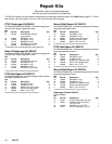
NOTE: Repair Kits are available to service the internal
parts of the fluid inlet and outlet. See page 14 for
ordering information. Parts included in the kits are
marked with three asterisks, for example (16***). The
kits include some parts which are not used on the
surge suppressor. Use all the applicable parts in the kit
for the best results.
1. Relieve the pressure.
WARNING
To reduce the risk of serious injury whenever you
are instructed to relieve pressure, always follow the
Pressure Relief Procedure on page 4.
2. Place a container under the surge suppressor,
disconnect the hoses, and turn the surge
suppressor on end to drain the fluid.
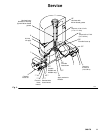
3. Remove the bolts (2), lockwashers (3), and nuts
(1) holding one manifold (9) to the cover (7).
Repeat for the other side. See Fig. 2.
4. Pull the two o-rings (16), guide (18) and stop (17)
out of the cover (7). Repeat for the other side.
Clean and inspect all parts for wear or damage.
5. Push one o-ring (16***) all the way into the cavity
of the cover (7). Install the stop (17***) with the
beveled side facing inward. Install the guide (18***)
with the flat end facing inward, then install the
second o-ring (16***) around the outer edge of the
guide. Repeat for the other side.
6. Install the manifold (9) on the cover (7) with the
chamfer facing outward. Secure with the bolts (2),
lockwashers (3), and nuts (1). Torque to 3 to 6 ft-lb
(4 to 8 N.m). Repeat for the other side.