


IT3800/3900 User’s Guide 13 - 3
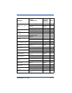
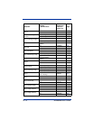
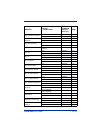
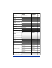
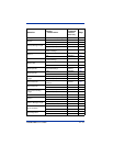
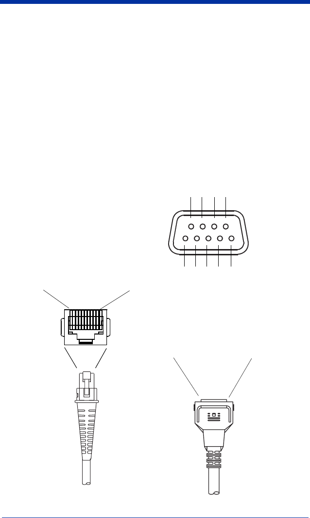
Standard Cable Pinouts
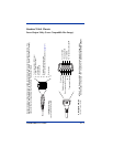
Laser Output Only (Laser Compatible Bar Image)
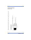
10 Pin Modular Plug
o
nnects to the scanner handle
1 Turn on good read or LED beeper
2 Trigger signal to decoder
3 Laser enable
4 Supply ground
5
6 Digital bar code data output
7 Power connection (Refer to table on page 13-1)
8
9 Start of scan
10
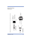
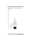
9 Pin Type D Female
connects to your terminal
◆ Pins 4 and 9 are populated depending on power supply voltage option.
Some decoders may have +12V on pins 4 or 9.
Connect to +5VDC ONLY!
Conventional laser data format is provided at the modular connector in the scanner handle. The
interface cable is terminated with a 10 pin modular plug, and a 9 pin Type D (squeeze to release)
connector that is compatible with all Hand Held Products terminals.
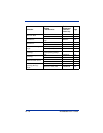
Start of scan
Digital bar code data output
Turn on good read LED or beeper
◆
N/C
Trigger signal to decoder
1
2
3
4
5
1
4
9
8
7
6
Laser enable
Supply ground
Cord shield
5 Volt power connection ◆