


B-45
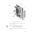
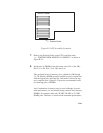
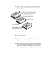
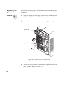
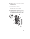
Next, align the bottom of the CPU Assembly with the guide on
the system unit. With the ejector latches in the open position,
slide the CPU Assembly into the system unit as far as it will go.
See Figure B–26.
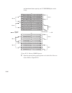
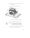
14. Press the ejector tabs all the way in and press on the left edge of
the processor module sheet metal to ensure that the processor
module is completely seated in the connector. Replace the two
screws in the center of the CPU Assembly. Make sure the ejec-
tors are completely depressed to ensure proper connector seating.
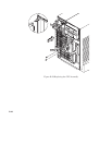
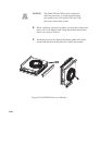
15. Close the system unit and reconnect all cables as described in the
“Closing the System Unit” section in this appendix.
16. To verify that this installation was successful, follow the steps in
Appendix D of this book, “The Boot Console Interface,” on dis-
playing memory information. If you have only replaced a faulty
DIMM, you must issue the pdt clear command in the service
menu of the Boot Console Interface. Answer yes (y) to the
prompt “Continue? (Y/N) >.”