


64
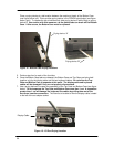
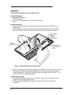
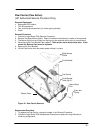
3. The Eject Buttons and Springs do not need to be removed to gain access to the Logic Board.
However, because they can be dislodged easily, setting them aside is recommended.
4. Remove the Paw Carrier Flex Cable from the zero-force insertion slot.
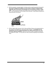
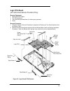
5. Remove the five (5) screws from the Logic Board (see previous illustration).
6. The Logic Board can now be lifted from the Bottom Case.
Replacement Procedure
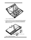
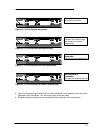
1. To replace the Logic Board, reverse the steps in the Removal Procedure. Ensure the Paw
Carrier flex cable is positioned properly – the end of the cable should be folded along the
holes in the cable. This folded portion then needs to be placed between the posts and
guided on the bottom case.
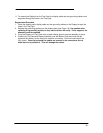
2. Follow the Display Replacement Procedure to replace the Display and remaining
components.