


380976 V3.1 6/08
13
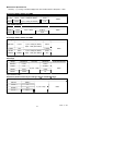
6.
W
3
φ
4W
= W
R(L1)
+ W
S(L2)
W
T(L3)
KVA K
W
KVARWW W34
2
34
2
34
φφ φ
=+
PF
K
W
KVA
W
W
W
34
34
34
φ
φ
φ
=
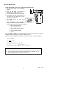
7. Set the rotary switch to another position to exit this mode and clear the stored data.
NOTE
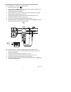
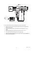
1. The "+" sign printed on meter must face the power source for accurate
measurement.
2. If the device under test is switching power supply, the KW, PF and
θ
readings
may not be correct.
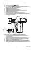
NOTE
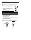
For 3
φ
4W power measurements, W
R
or W
S
and W
T
must be positive. If one shows
negative power, check the connections.
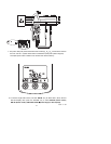
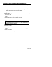
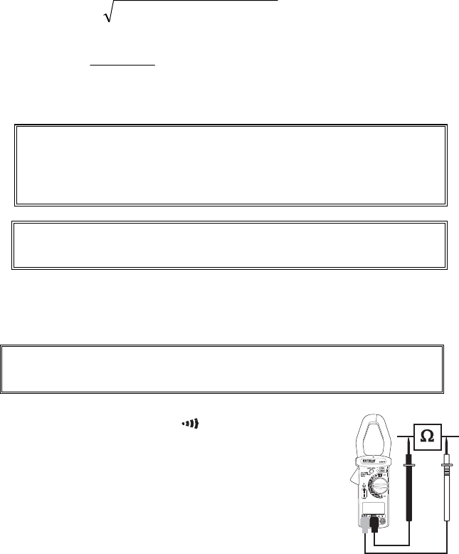
Resistance and Audible Continuity Measurements
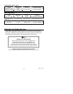
WARNING
Before taking any in-circuit resistance measurements remove power from the circuit
under test and discharge all capacitors.
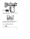
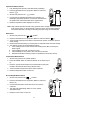
1. Set the rotary switch to the
‘Ω, ’
’
or ‘MΩ
’ position.
2. Insert the test leads into the input jacks. (Black to ‘COM’ and
Red to ‘
Ω’
)
3. Connect the test leads to the circuit or component under test.
4. Read the resistance value on the LCD.
5. For measurements < 40
Ω
, the continuity beeper will sound.