


380976 V3.1 6/08
14
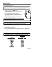
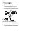
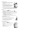
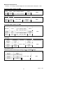
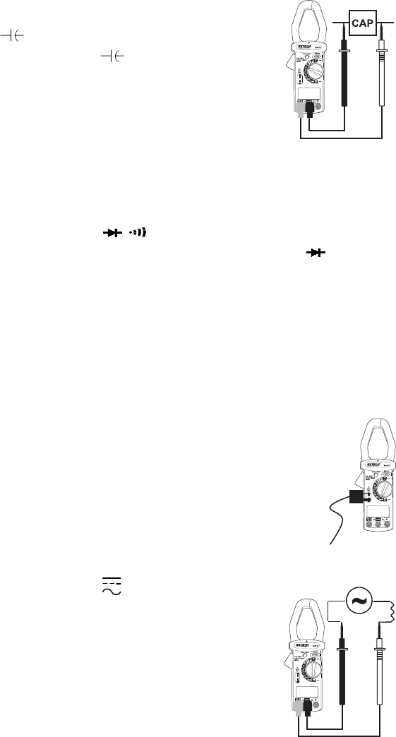
Capacitance Measurements
1. Fully discharge the capacitor under test before proceeding.
2. Insert the test leads into the input jacks. (Black to ‘COM’ and
Red to ‘
’).
3. Set the rotary switch to the ‘
’ position.
4. Connect the red and black test leads to the capacitor. For
Electrolytic (polarized) capacitors, connect the red test lead to
the positive side and the black lead to the negative side.
5. Read the capacitance value displayed on the LCD.
Note: Large valued capacitors will take a long period of time to charge and to auto-range
to the correct range. (up to 60 seconds in the worst case). For improved resolution
and shortest test time, manually pre-selecting the proper range is recommended.
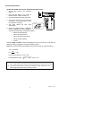
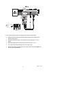
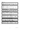
Diode Tests
1. Set the rotary switch to the "
" position.
2. Insert the test leads into the input jacks. (Black to ‘COM’ and Red to ‘
’)
3. Touch the test probe tips to the diode or semiconductor junction under test. Note the
meter reading.
4. Reverse the test lead polarity by reversing the red and black leads. Note this reading.
5. The diode or junction can be evaluated as follows:
a. If one reading shows a value and the other reading shows ‘OL’ (overload), the
diode is good.
b. If both readings show ‘OL’, the device is open.
c. If both readings are very small or zero, the device is shorted.
d. Note that the audible continuity function is operational in this mode (<40mV).
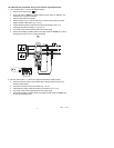
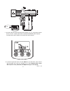
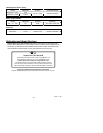
Temperature Measurements
1. Set the rotary switch to the "TEMP" position.
2. Press the RANGE button to select the desired unit of measure (C or
F).
3. Insert the Type K Thermocouple into the subminiature input jacks
located to the lower left of the rotary selector switch.
4. Touch the thermocouple sensor to the object under test.
5. Read the temperature value on the LCD.
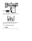
AC and DC
µA
Measurements
1. Set the rotary switch to the "
µA
" position.
2. Insert the test leads into the input jacks. (Black to ‘COM’ and
Red to ‘
µA’)
3. Connect the test leads in series with the circuit or device
under test.
4. The meter will automatically select AC or DC and the
appropriate range.
5. Read the current value on the LCD.