


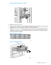


module B port 2 of the newly installed drive enclosure (3, Figure 13 (page 9)). In addition, a
new Fibre Channel copper cable is installed between I/O Module B port P2 of the preexisting
drive enclosure and I/O module B port 1 of the newly installed drive enclosure (4).
7. Verify that I/O modules A and B on the added enclosure have been assigned an index number
of the next higher enclosure number. For example, if the previous highest index number was “3,”
then the installed enclosure should display “4.”
8. In HP P6000 Command View, verify that the newly installed drive enclosure appears in the array
hardware pane, and that the I/O modules show a good operational status.
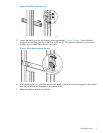
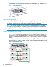
Alternate enclosure cabling
Drive enclosures may have to be installed where room is available in a cabinet. Figure 12 (page 8)
and Figure 13 (page 9) show drive enclosures mounted in a cabinet on just one side of the controller
enclosure. When drive enclosures are mounted on both sides of the controller enclosure, the cabling
is logically the same, in that all the drive enclosures are connected serially. In this case, the long Fibre
Channel cable goes from the I/O module P2 port of the last drive enclosure on one side of the controller
enclosure to the farthest drive enclosure on the other side of the controller enclosure. The last drive
enclosure in the series (near the controller enclosure) completes the loop back to the controller.
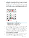
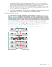
Figure 14 (page 11) shows this cabling configuration with drive enclosures above and below the
controller enclosure in an array. Installing a drive enclosure above or below this configuration would
keep the same pattern of cabling between the drive and controller enclosures.
Figure 14 Array cabling for drive enclosures on both sides of the controller enclosure
Cabling the enclosure 11