


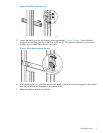


2. Figure 13 (page 9) shows the cabling when another drive enclosure is added to the bottom of
the array. The dashed lines leading to the controller enclosure show cables that are moved, and
dashed lines between the drive enclosures show cables that are added.
Unplug the Fibre Channel cable from I/O module A port P2 of the drive enclosure nearest the
newly installed drive enclosure, and plug it into the P2 port of I/O module A of the newly installed
drive enclosure (1, Figure 13 (page 9)). This should be a long cable with the far end connecting
to controller 2 port DP1–A in a configuration with all the drive enclosures installed above or below
the controller enclosure. If drive shelves are installed above and below the controller enclosure,
see Figure 14 (page 11).
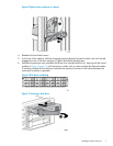
Figure 13 Addition of drive enclosure to array
Connects installed I/O module A, port 2 to controller 2, port DP1–A1
Connects installed I/O module A, port 1 to existing I/O module A, port 22
Connects installed I/O module B, port 2 to controller 1, port DP1–B3
Connects installed I/O module B, port 1 to existing I/O module B, port 24
3. Using a Fibre Channel copper cable provided in your kit, plug one end into the P2 port of I/O
module A that was unplugged in the previous step, and plug the other end into port P1 of
I/O module A in the newly installed drive enclosure (2, Figure 13 (page 9)).
4. Perform steps 2 and 3 on I/O module B of the newly installed drive enclosure. The results are the
Fibre Channel cable on I/O Module B port 2 of the nearest drive enclosure is moved to I/O
module B port 2 of the newly installed drive enclosure (3, Figure 13 (page 9)). In addition, a
new Fibre Channel copper cable is installed between I/O Module B port P2 of the preexisting
drive enclosure and I/O module B port 1 of the newly installed drive enclosure (4).
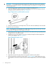
5. Using a power cord provided in your kit, plug one end into a drive enclosure power supply and
the other end into a cabinet power distribution module.
6. With the remaining power cord, connect the other power supply to a cabinet power distribution
module.
7. Press the Power On/Standby button on the power UID bezel (located at the rear of the drive
enclosure) and hold it down long enough to power up the installed enclosure.
Cabling the enclosure 9