


OSPF
137
Electing the designated router and backup
In any area with more than two routing devices, a Designated Router (DR) is elected as the central contact
for database exchanges among neighbors, and a Backup Designated Router (BDR) is elected in case the
DR fails.
DR and BDR elections are made through the hello process. The election can be influenced by assigning a
priority value to the OSPF interfaces on the switch. The command is as follows:
>>#/cfg/l3/ospf/if <OSPF interface number>/prio <priority value (0-255)>
A priority value of 255 is the highest, and 1 is the lowest. A priority value of 0 specifies that the interface
cannot be used as a DR or BDR. In case of a tie, the routing device with the lowest router ID wins.
Summarizing routes
Route summarization condenses routing information. Without summarization, each routing device in an
OSPF network would retain a route to every subnet in the network. With summarization, routing devices
can reduce some sets of routes to a single advertisement, reducing both the load on the routing device
and the perceived complexity of the network. The importance of route summarization increases with
network size.
Summary routes can be defined for up to 16 IP address ranges using the following command:
>> # /cfg/l3/ospf/range <range number>/addr <IP address>/mask <mask>
where <range number> is a number 1 to 16, <IP address> is the base IP address for the range,
and <mask> is the IP address mask for the range.
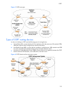
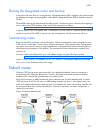
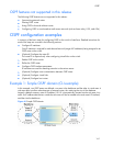
Default routes
When an OSPF routing device encounters traffic for a destination address it does not recognize, it
forwards that traffic along the default route. Typically, the default route leads upstream toward the
backbone until it reaches the intended area or an external router.
Each switch acting as an ABR automatically inserts a default route into each attached area. In simple
OSPF stub areas or NSSAs with only one ABR leading upstream (see Area 1 in the figure below), any
traffic for IP address destinations outside the area is forwarded to the switch’s IP interface, and then into
the connected transit area (usually the backbone). Since this is automatic, no further configuration is
required for such areas.
Figure 19 Injecting default routes