


High availability
169
Configuration guidelines
This section provides important information about configuring UFD:
• UFD is required only when uplink-path redundancy is not available on the blade switches.
• Only one Failure Detection pair (one group of Links to Monitor and one group of Links to Disable) is
supported on each switch (all VLANs and Spanning Tree Groups).
• An LtM can be either one uplink port or one Multi-Link trunk group of uplink ports.
• Ports that are already members of a trunk group are not allowed to be assigned to an LtM.
• A trunk group configured as an LtM can contain multiple uplink ports (18-21), but no downlink
ports (1-16).
• An uplink port cannot be added to a trunk group if it already belongs to an LtM.
• An LtD can contain one or more ports, and/or one or more trunks
• A trunk group configured as an LtD can contain multiple downlink ports (1-16), but no uplink
ports (18-21).
Monitoring Uplink Failure Detection
The UFD information menu displays the current status of the LtM and LtD, and their member ports or
trunks. For example:
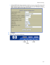
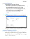
>> Information# ufd
Uplink Failure Detection: Enabled
LtM status: Down
Member STG STG State Link Status
--------- --- ------------ -----------
port 19 down
1 DISABLED
10 DISABLED *
15 DISABLED *
* = STP turned off for this port.
LtD status: Auto Disabled
Member Link Status
--------- -----------
port 1 disabled
port 2 disabled
port 3 disabled
port 4 disabled
Use the /stats/ufd command to find out how many times link failure was detected on the LtM, how
many times Spanning Tree blocking state was detected on the LtM, and how many times UFD disabled
ports in the LtD.
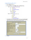
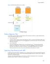
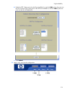
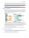
Configuring Uplink Failure Detection
The preceding figure shows a basic UFD configuration. Assume that port 19 on Blade Switch 1 is
connected to a Layer 2/3 routing switch outside of the chassis. Port 18 and port 19 on Blade Switch 2
form a trunk that is connected to a different Layer 2/3 routing switch.
In this example, NIC 1 is the primary network adapter; NIC 2, NIC 3, and NIC 4 are non-primary
adapters. NIC 1 and NIC 2 are connected to port 1 and port 2 on Blade Switch 1. NIC 3 and NIC 4 are
connected to port 1 and port 2 on Blade Switch 2.