


RSTP and MSTP
80
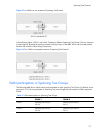
3. Apply, verify, and save the configuration.
Multiple Spanning Tree Protocol
IEEE 802.1s Multiple Spanning Tree extends the IEEE 802.1w Rapid Spanning Tree Protocol through
multiple Spanning Tree Groups. MSTP maintains up to 32 spanning-tree instances that correspond to STP
Groups 1-32.
In Multiple Spanning Tree Protocol (MSTP), several VLANs can be mapped to each Spanning-Tree
instance. Each Spanning-Tree instance is independent of other instances. MSTP allows frames assigned to
different VLANs to follow separate paths, each path based on an independent Spanning-Tree instance.
This approach provides multiple forwarding paths for data traffic, enabling load balancing, and reducing
the number of Spanning-Tree instances required to support a large number of VLANs.
MSTP region
A group of interconnected bridges that share the same attributes is called an MST region. Each bridge
within the region must share the following attributes:
• Alphanumeric name
• Revision level
• VLAN-to-STG mapping scheme
MSTP provides rapid reconfiguration, scalability, and control due to the support of regions, and multiple
Spanning-Tree instances support within each region.
Common Internal Spanning Tree
The Common Internal Spanning Tree (CIST) provides a common form of Spanning Tree Protocol, with one
Spanning Tree instance that can be used throughout the MSTP region. CIST allows the switch to
interoperate with legacy equipment, including devices that run IEEE 802.1d (STP).
CIST allows the MSTP region to act as a virtual bridge to other bridges outside of the region, and
provides a single Spanning-Tree instance to interact with them.
CIST is the default spanning tree group. When VLANs are removed from STG 1-128, the VLANs
automatically become members of the CIST.
CIST port configuration includes Hello time, Edge port status (enable/disable), and Link Type. These
parameters do not affect Spanning Tree Groups 1-128. They apply only when the CIST is used.