


Installing and Removing Drives
When installing drives, follow these guidelines:
●
The primary Serial ATA (SATA) hard drive must be connected to the dark blue primary SATA
connector on the system board labeled SATA0. If you are adding a second hard drive, connect it
to the white connector on the system board labeled SATA1.
●
Connect a SATA optical drive to the white SATA connector on the system board labeled SATA2.
●
Connect an optional eSATA adapter cable to the black SATA connector on the system board
labeled ESATA.
●
Connect a media card reader USB cable to the USB connector on the system board labeled
MEDIA.
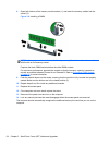
● The power cable for the SATA drives is a three-headed cable that is plugged into the system
board with the first connector routed to the rear of the hard drive, the second connector routed to
the rear of the 3.5” drive, and the third connector routed to the rear of the 5.25” optical drive.
●
The system does not support Parallel ATA (PATA) optical drives or PATA hard drives.
●
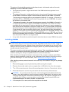
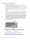
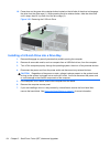
You must install guide screws to ensure the drive will line up correctly in the drive cage and lock
in place. HP has provided extra guide screws for the drive bays (five 6-32 standard screws and
four M3 metric screws), installed in the front of the chassis, under the front bezel. The 6-32
standard screws are required for a secondary hard drive. All other drives (except the primary
hard drive) use M3 metric screws. The HP-supplied metric screws are black and the HP-
supplied standard screws are silver. If you are replacing the primary hard drive, you must
remove the four silver and blue 6-32 isolation mounting guide screws from the old hard drive and
install them in the new hard drive.
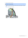
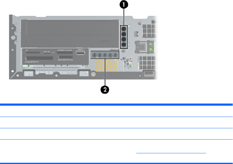
Figure 3-17 Extra Guide Screw Locations
No. Guide Screw Device
1 Black M3 Metric Screws All Drives (except primary and secondary hard drives)
2 Silver 6-32 Standard Screws Secondary Hard Drive
There are at total of five extra silver 6-32 standard screws. Four are used as guide screws for a
secondary hard drive. The fifth is used for bezel security (see
Front Bezel Security on page 80 for more
information).
60 Chapter 3 Small Form Factor (SFF) Hardware Upgrades