


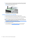
Installing a 3.5-inch Drive into a Drive Bay
The 3.5-inch bay is located underneath the 5.25-inch drive. To install a drive into the 3.5-inch bay:
NOTE: Install guide screws to ensure the drive will line up correctly in the drive cage and lock in
place. HP has provided extra guide screws for the drive bays (four 6-32 standard screws and four M3
metric screws), installed in the front of the chassis, under the front bezel. A secondary hard drive
uses 6-32 standard screws. All other drives (except the primary hard drive) use M3 metric screws.
The HP-supplied M3 metric screws are black and the HP-supplied 6-32 standard screws are silver.
Refer to
Installing and Removing Drives on page 60 for illustrations of the guide screw locations.
1. Follow the procedure in Removing a 5.25-inch Drive from a Drive Bay on page 62 to remove the
5.25-inch drive and access the 3.5-inch drive bay.
CAUTION: Ensure that the computer is turned off and that the power cord is disconnected
from the electrical outlet before proceeding.
2. If you are installing a drive in a bay covered by a bezel blank, remove the front bezel then
remove the bezel blank. See
Removing Bezel Blanks on page 47 for more information.
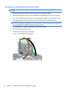
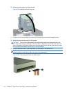
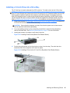
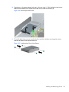
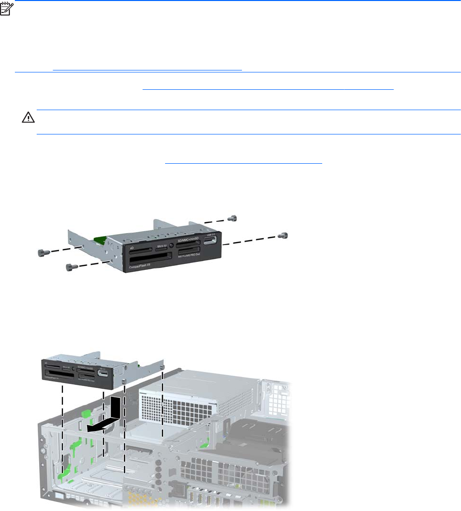
3. Install guide screws in the holes on each side of the drive.
Figure 3-29 Installing Guide Screws (Media Card Reader Shown)
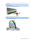
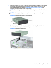
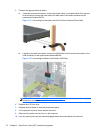
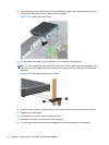
4. Position the guide screws on the drive into the J-slots in the drive bay. Then slide the drive
toward the front of the computer until it locks into place.
Figure 3-30 Installing a Drive into the 3.5-inch Drive Bay (Media Card Reader Shown)
Installing and Removing Drives 69