


10
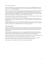
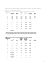
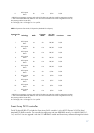
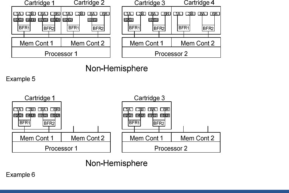
The above Non-Hemisphere Example 5 and Example 6 illustrate:
Each memory controller must have a memory cartridge
DIMM configurations of each memory cartridge connected to controller 1 and 2 of a processor must be identical.
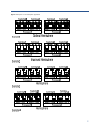
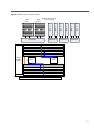
Note that “Example 4” is a Hemisphere configuration. The two cartridges connected to each processor share
identical configurations, but Cartridge 1 and Cartridge 2 are not identical to Cartridge 3 and Cartridge 4.
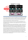
Increasing memory performance
For improved performance, successive cache lines interleave between the DIMMs and the lockstep SMI channels of
the processor’s two memory controllers. This alternate-layer arrangement of cache lines boosts performance by
allowing adjacent cache lines to reside on different memory controllers, different SMIs, different DIMMs, and DIMM
ranks. SMI channel DIMMs are evenly populated. If a given SMI channel pair has more DIMMs than other
channels, the extra memory will not receive the benefit of the interleaving mechanism.
Achieving optimum performance
The DL580 G7 supports 64 DIMMs slots across four multi-core processors. While there are multiple DIMM
population configurations that may support the desired total memory size, you can only achieve optimal
performance when populating DIMMs that can take advantage of the Intel Xeon Processor E7 and 7500 series
architecture.
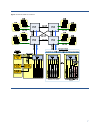
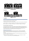
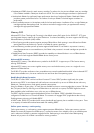
The Hemisphere Population Diagram (Figure 3) displays how to achieve the best performance for a given memory
and processor configuration. Follow these rules:
Use both memory controllers inside the processor and populate two memory cartridges for each installed
processor. This is the top contributor to memory bandwidth performance.