


Introduction
14 HP StorageWorks 2/8q Fibre Channel Switch Installation Guide
Power supply
The power supply converts standard 110 or 230 VAC to DC voltages for the various switch
circuits. Four internal fans provide cooling. The switch monitors internal air temperature, and
therefore does not monitor or report fan operational status. Air flows into the switch from the
bezel side and is exhausted from the port side of the switch.
To apply power to the switch, plug the power cord into the switch AC receptacle, and then into
a 110 or 230 VAC power source.
Note: The power supply and fans are not field replaceable units.
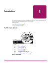
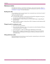
Serial port
The switch is equipped with an RS-232 serial port, to access the Command Line Interface for
advanced configuration tasks and maintenance purposes. (Figure 1)
The serial port connector requires a null-modem female/female DB9 cable, using the pin
configuration and connection information as detailed in “Cable pin configurations” on
page 64.
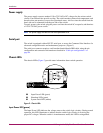
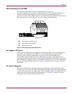
Chassis LEDs
The chassis LEDs (Figure 2) provide status information about switch operation.
Figure 2: Chassis LEDs
Input Power LED (green)
The Input Power LED indicates the voltage status at the switch logic circuitry. During normal
operation, this LED illuminates to indicate that the switch logic circuitry is receiving the
proper DC voltages. When the switch is in maintenance mode, this LED is extinguished.
1 Input Power LED (green)
2 Heartbeat LED (green)
3 System Fault LED (amber)
1
2
3