


4. Remove the battery (see Battery on page 47).
5. Remove the following:
a. Hard drive (see
Hard drive on page 53)
b. Optical drive (see
Optical drive on page 56)
c. Keyboard (see
Keyboard on page 61)
d. Switch cover (see
Switch cover on page 66)
e. Fan (see
Fan on page 68)
f. Heat sink (see
Heat sink on page 69)
g. Display assembly (see
Display assembly on page 75)
h. Top cover (see
Top cover on page 81)
i. ExpressCard board (see
ExpressCard board on page 84)
j. Audio board (see
Audio board on page 85)
k. Speaker (see
Speaker on page 88)
l. Rear cover (see
Rear cover on page 92)
m. SIM connector board (see
SIM connector board on page 94)
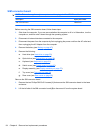
When replacing the system board, be sure that the following components are removed from the defective
system board and installed on the replacement system board:
●
SIM (see
SIM on page 48)
●
RTC battery (see
RTC battery on page 55)
●
Memory modules (see
Primary memory module on page 64 and Expansion memory module
on page 57)
●
WLAN module (see
WLAN module on page 59)
●
WWAN module (see
WWAN module on page 65)
●
Processor (see
Processor on page 73)
●
Optical drive connector board (see
Optical drive connector board on page 101)
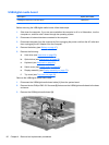
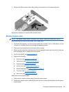
Remove the system board:
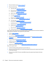
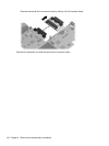
1. Position the base enclosure with the rear panel toward you.
2. Remove the two Phillips PM2.5×3.0 broad-head screws (1) that secure the system board bracket
to the base enclosure.
3. Remove the two HM5.0×9.0 screw locks (2) that secure the system board bracket to the base
enclosure.
98 Chapter 4 Removal and replacement procedures