


NOTE: The hard drive uses 6-32 isolation mounting guide screws. Four extra guide screws are
installed on the exterior of the hard drive bays. The HP-supplied isolation mounting guide screws
are silver and blue. Refer to
Installing and Removing Drives on page 72 for an illustration of the
extra 6-32 isolation mounting guide screws location.
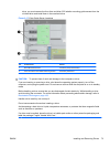
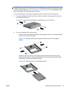
If you are replacing a drive, transfer the guides screws from the old drive to the new one.
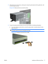
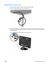
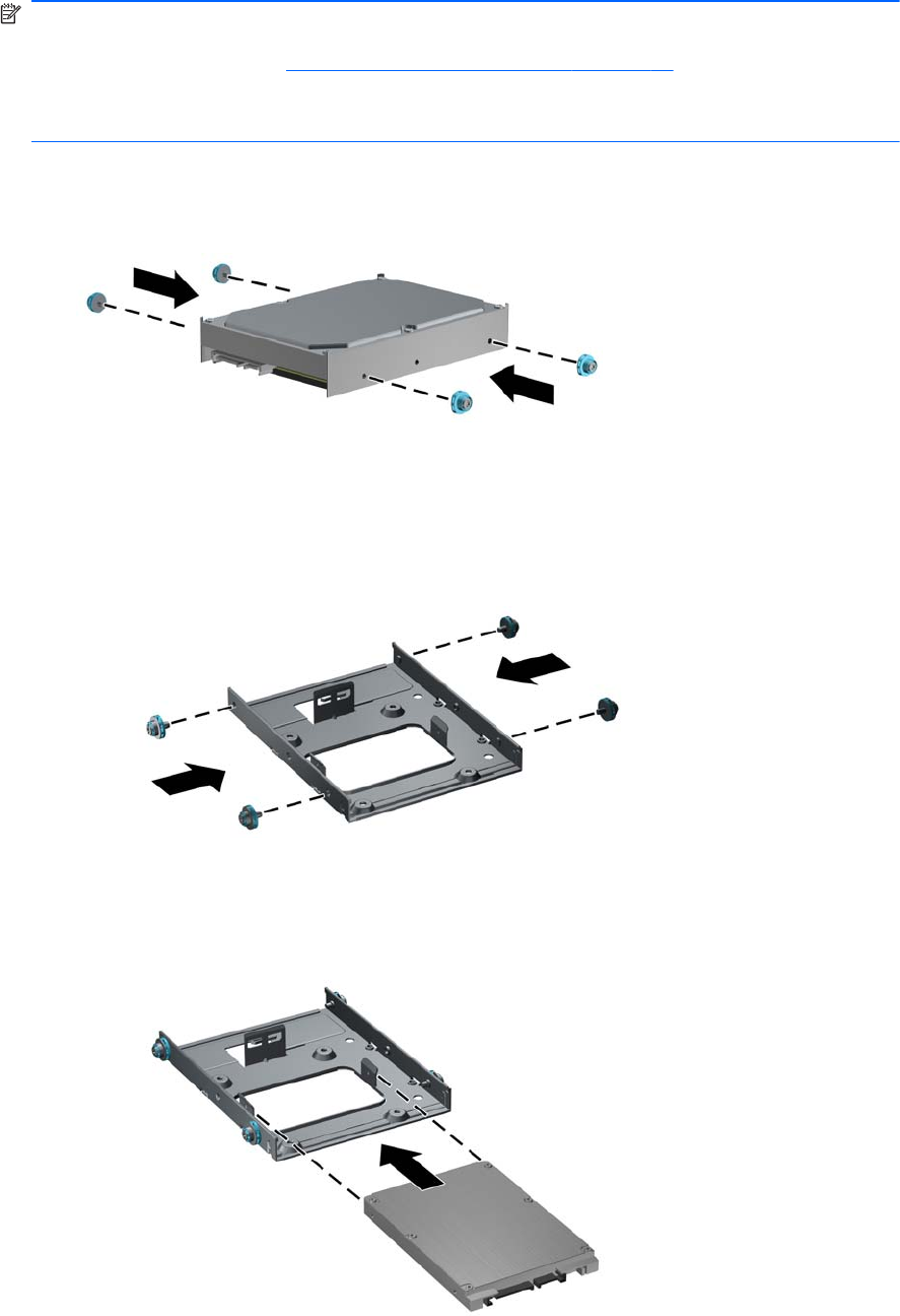
● If you are installing a 3.5-inch hard drive, install four isolation mounting guide screws (two
on each side of the drive).
Figure 3-27 Installing Isolation Mounting Guide Screws in a 3.5-inch Drive
●
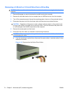
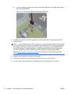
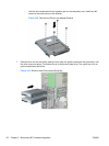
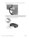
If you are installing a 2.5-inch hard drive:
◦
Install four 6-32 silver and blue isolation mounting guide screws in the adapter bracket
(two on each side of the bracket).
Figure 3-28 Installing Isolation Mounting Guide Screws in the 2.5-inch Adapter
Bracket
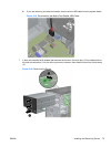
◦
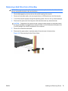
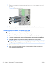
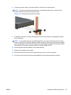
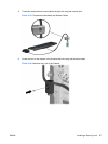
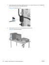
Install the drive into the slot on the adapter bracket with the PCA side facing down,
aligning the three tabs on the bracket with the drive. Ensure that the power and data
connectors on the drive are properly oriented.
Figure 3-29 Installing the Drive in the Adapter Bracket
ENWW Installing and Removing Drives 81