


2 Aligning the Bracket
Figure 2-1 “Bracket Orientation” shows the correct orientation of the cable management bracket which
youmust install before connectingthe cables to the InfiniBandswitch module. During the cablingprocedure,
the bracket provides strain relief for the InfiniBand ports, and maintains the correct minimum cable bend
radius.
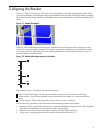
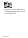
Figure 2-1 Bracket Orientation
Callout 1 shows the bracket's mounting hook, installed in one of the square holes in the left rear rack
column. The actual mounting locations for a bracket are relevant to the location of the blades enclosure
in the rack, and must align with the switch module installed in the c-Class blade enclosure. Figure 2-2
identifies relative mount locations.
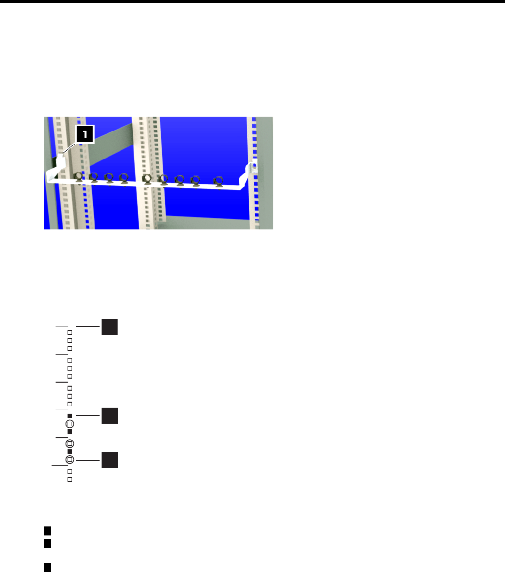
Figure 2-2 Relative Mounting Locations for a Bracket
U10
U9
U8
U7
U6
1
3
2
The callouts in Figure 2-2 identify the following features:
1
The U location that aligns with the top of the blades enclosure. Each enclosure us 10U high.
2
Filled squares – One of three potential cutouts (mounting holes) where you mount the bracket's
hook.
3
Circled squares – One of three potential cutouts where you locate a fastener.
Use the following procedure to determine the actual mounting locations for brackets:
1. Determine which of the blades chassis bays contain the InfiniBand switch modules. (There might be
more than one InfiniBand switch module in some configurations).
2. Determine the rack U location that aligns with the top of the blades enclosure.
3. Using a pen or masking tape, mark the mount locations defined in Table 2-1.
5