


3 Installing and Using the Bracket
One bracket is required for each 8–port InfiniBand switch module, typically installed in bays 3 and 4 of
the c-Class server blade enclosure in HP Cluster Platform. When installed, the bracket occupies less than
1U (1.75 inches) of rack column space.
Use the following procedure to install the c-Class server blade enclosure cable management bracket:
CAUTION: When performing the installation procedure, extend only one blade enclosure no more than
a few inches from the rack at any time. Ensure that the rack is stable before you begin the installation
procedure.
1. Starting from the lowest bracket, using the fastener locations that you identified and marked in
Chapter 2 (page 5), clip a cage nut into the back of each rear rack column.
2. Hook the bracket onto the square cutouts in the rack column.
3. Fastenbracket to the rearrack columns by usingtwo M6 pan-head screws and tighten to thespecified
torque.
4. Repeat Steps 1 through 3 if more than one bracket is required.
5. Slidethe blade enclosure into the rack and secure it at the front of the rack as specified in the installation
instructions for the blade enclosure.
6. Starting at the lowest port and working up through the rack, consult the cabling tables for your HP
Cluster Platform solution and begin connecting the cables.
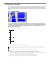
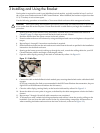
7. Open the cable clips by pressing in the latch as indicated by callout 1 in Figure 3-1.
Figure 3-1 Cable Clips
8. Connectthe cable to the InfiniBand switch module port, ensuring that the latch on the cable head-shell
engages.
(If youare connecting live links, as recommended in the HP ClusterPlatform documentation, the port
signal LEDs will illuminate and indicate the link status.)
9. Close the cable clip by pressing firmly on the location indicated by callout 2 in Figure 3-1.
10. Route the cable to its next point of support, as defined by the cable management solution for blades
clusters.
11. Repeat steps 7 through 10 until all cable connections are completed.
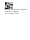
12. To disconnect a cable, unlatch its locking mechanism and remove it from the port by pulling on the
headshell. (You can leave the cable secured in the clip when making a temporary disconnection or
when extending the blades enclosure from the front of the rack, as shown in Figure 3-2.)
7