


Index-2 www.hp.com Hardware Reference Guide
Index
replacing 2–22
restoring
2–25
SATA connectors
2–13
headphone jack
1–2
headphone line-out connector
1–3
I
installation guidelines 2–13
installing
battery
B–1
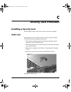
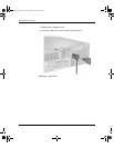
cable lock
C–1
expansion card
2–10
guide screws
2–18
hard drive
2–26
hard drive in 3.5-inch bay
2–25
memory
2–5
optical drive
2–18
padlock
C–3
K
keyboard
components
1–4
connector
1–3
L
locks
cable lock
C–1
padlock
C–3
M
memory
Asymetric mode
2–6
capacity
2–5, 2–6, 2–9
identifying modules
2–9
identifying sockets
2–7
installing
2–5
Interleaved mode
2–6
populating sockets
2–6
single channel mode
2–6
specifications
2–5
microphone connector
1–2
monitor, connecting
1–3
mouse
connector
1–3
special functions
1–5
O
optical drive
activity light
1–2
cleaning
D–2
connecting cables
2–21
eject button
1–2
guide screws
2–18
guidelines
D–2
installing
2–18
location
1–2
precautions
D–2
removing
2–15
P
padlock, installing C–3
Parallel ATA devices
2–13
parallel connector
1–3
PCI card
See expansion card
power
button
1–2
cord connector
1–3
indicator light
1–2
power supply
2–23, A–2
R
rear panel components 1–3
removing
bezel
2–27
computer cover
2–3
diskette drive
2–15
expansion slot cover
2–11
hard drive
2–24
optical drive
2–15
RJ-45 connector
1–3
376293-002.book Page 2 Friday, February 18, 2005 3:02 PM