


Component identification 11
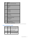
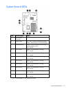
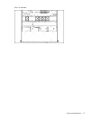
Item Description
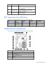
6 Dedicated iLO 2 module connector (optional)
7 NMI jumper
8 System battery
9 TPM connector
10 DIMM slots 1-9
11 Reserved
12 System power connector
13 Fan 1 connector
14 Fan 2 connector
15 Processor socket
16 Fan 3 connector
17 Fan 4 connector
18 Fan 5 connector*
19 Power connector
20 Front USB connector
21 Hard drive backplane connector
22 USB tape drive connector
23 Redundant power supply connector
24 Front panel connector
25 Fan 7 connector
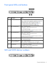
26 SATA connectors 1-4 (hard drives)
27 Hard drive backplane connector
28 System maintenance switch
29 SATA connectors 5-6 (optical drives)**
* Fan 5 is only available in CTO models of this server.
**The server supports one optical drive that can be connected to either SATA connector 5 or SATA connector 6.
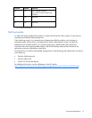
System maintenance switch
Position Default Function
S1 Off Off = iLO 2 security is enabled
On = iLO 2 security is disabled
S2 Off Off = Normal operation
On = RBSU will not commit any
configuration changes*
S3 Off Reserved
S4 Off Reserved
S5 Off Off = Power-on password enabled
On = Power-on password disabled*