


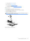
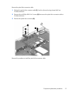
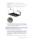
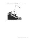
c.
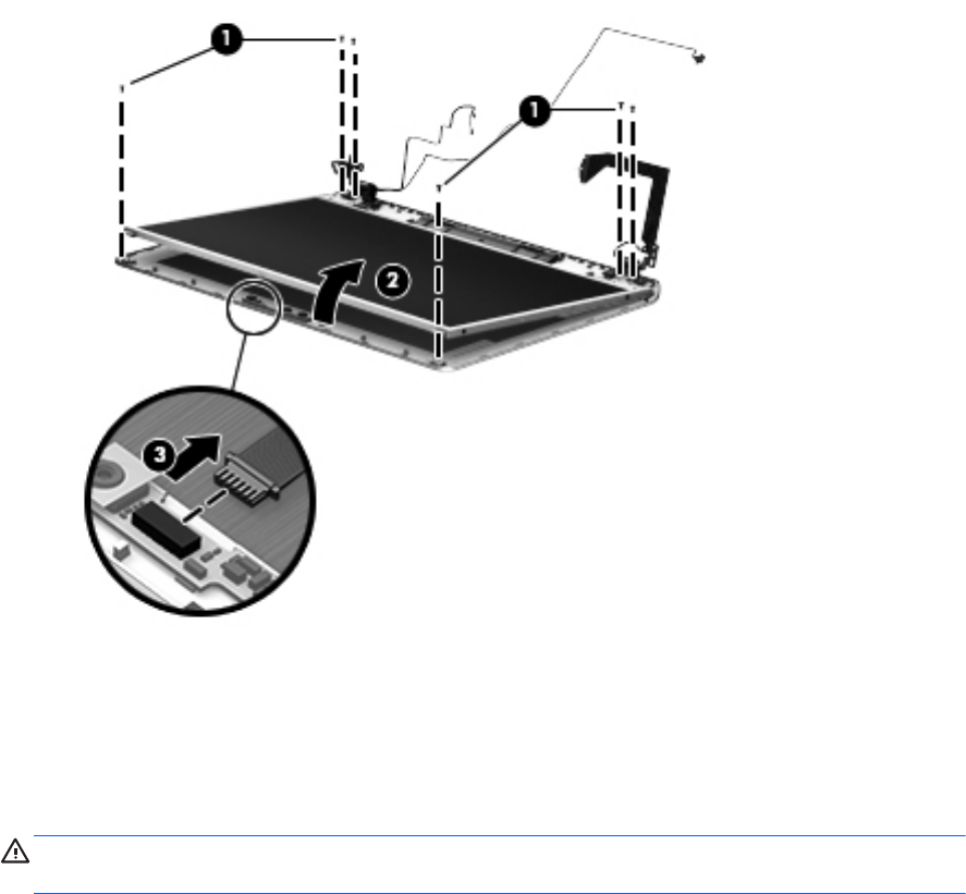
Remove the six Phillips PM2.0×6.0 screws (1) that secure the display panel to
the display enclosure.
d. Lift the top edge of the display panel (2) until the webcamera/microphone module connector
is accessible.
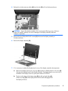
e. Disconnect the webcamera/microphone module cable (3) from the webcamera/
microphone module.
f. Remove the display panel (2) from the display enclosure. The display panel is available
using spare part numbers 681991-001 (for use only on computer models equipped with a
17.3-in, AntiGlare, FHD display panel) and 681990-001 (for use only on computer models
equipped with a 17.3-in, BrightView, HD display panel).
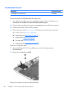
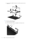
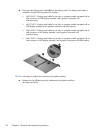
9. If it is necessary to replace the display panel cable:
CAUTION: Be sure the work surface is clear of all tools, screws, and computer components
before turning the display panel upside down on the work surface.
a. Turn the display panel upside down, with the top edge toward you.
b. Detach the webcamera/microphone module cable (1) from the rear surface of the display
panel. (The webcamera/microphone module cable is attached to the display panel by
double-sided tape.) Detach the display panel cable (2) from the rear surface of the display
panel. (The display panel cable is attached to the display panel by double-sided tape.)
Release the adhesive support strip (3) that secures the display panel cable connector to
the display panel.
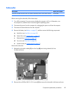
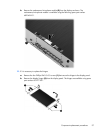
c. Release the handle (4) that secures the display panel cable connector to the display panel.
Component replacement procedures
95