


c.
Keyboard (see
Keyboard on page 59)
d. Top cover (see
Top cover on page 63)
e.
System board (see
System board on page 77)
Remove the fan/heat sink assembly:
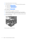
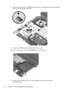
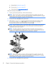
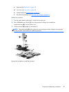
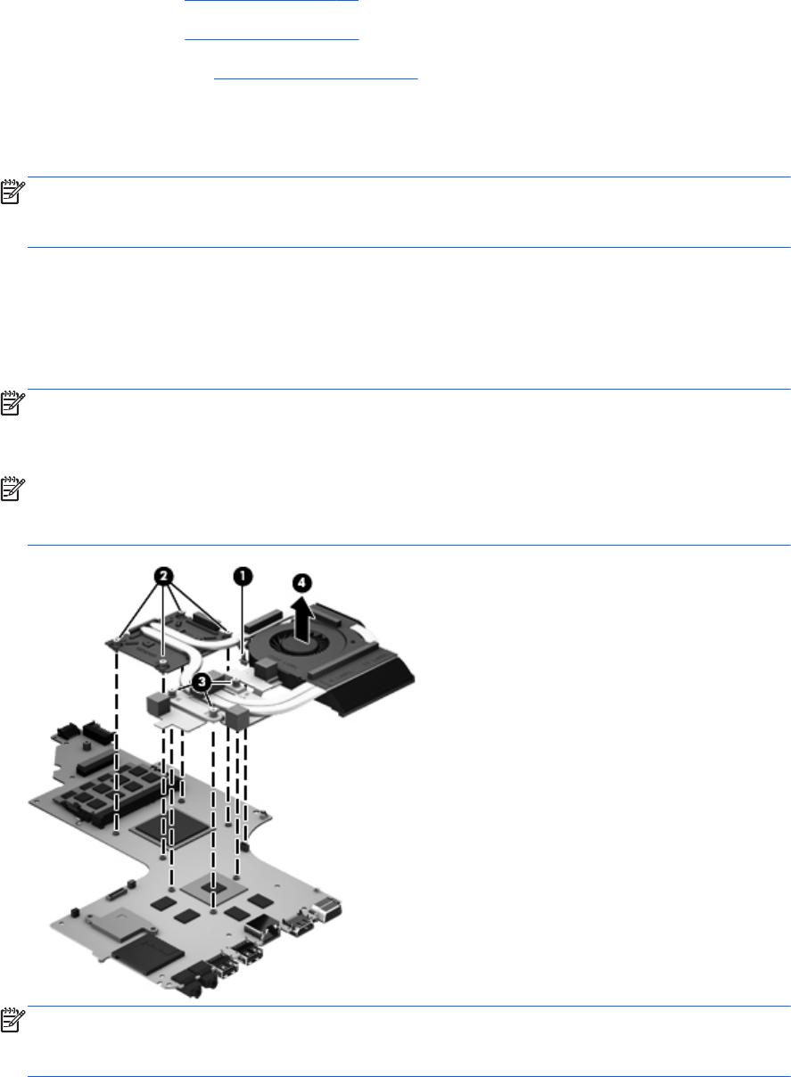
1. Turn the system board upside down, with the front toward you.
NOTE: Steps 2 and 3 apply to computer models equipped with a graphics subsystem with
discrete memory. See steps 4 and 5 for fan/heat sink assembly removal information for computer
models equipped with a graphics subsystem with UMA memory.
2. Disconnect the fan cable (1) from the system board.
3. Following the 1, 2, 3, 4, 5, 6, 7 sequence stamped into the fan/heat sink assembly, loosen
the seven captive Philllips screws (2) and (3) that secure the fan/heat sink assembly to
the system board, and then remove the fan/heat sink assembly (4).
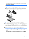
NOTE: Due to the adhesive quality of the thermal material located between the fan/heat sink
assembly and the system board components, it may be necessary to move the fan/heat sink
assembly from side to side to detach it.
NOTE: The following illustration shows the fan/heat sink assembly removal process for a
computer model equipped with an AMD processor. The process for removing the fan/heat sink
assembly on a computer model equipped with an Intel processor is identical.
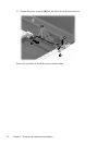
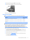
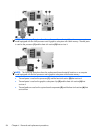
NOTE: Steps 4 and 5 apply to computer models equipped with a graphics subsystem with
UMA memory. See steps 2 and 3 for fan/heat sink assembly removal information for computer
models equipped with a graphics subsystem with discrete memory.
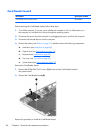
4. Disconnect the fan cable (1) from the system board.
82 Chapter 4 Removal and replacement procedures