


5–22 Maintenance and Service Guide
Removal and Replacement Procedures
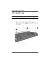
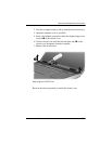
5.10 Switch Cover
1. Prepare the computer for disassembly (Section 5.3).
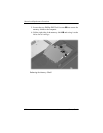
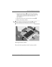
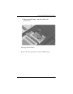
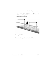
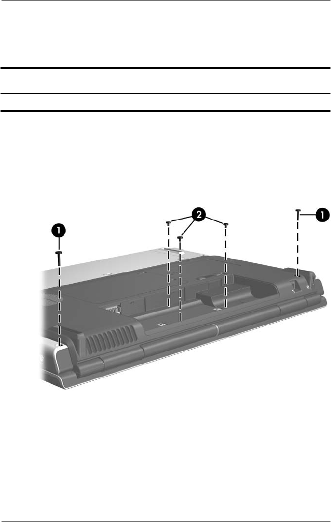
2. Remove the two Phillips PM2.5×13.0 screws 1 and the three
Phillips PM2.5×4.0 screws 2 that secure the switch cover to
the computer.
Removing the Switch Cover Screws
Switch Cover Spare Part Number Information
Switch cover (includes LED board and LED board cable) 403817-001