


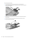
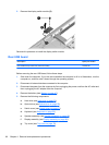
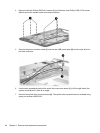
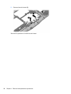

4. Remove the three Phillips PM2.5×8.0 screws (1) and the three silver Phillips PM2.5×5.0 screws
(2) that secure the system board to the base enclosure.
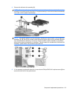
5. Remove the power connector cable (1) and the rear USB board cable (2) from the clips built into
the base enclosure.
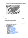
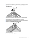
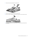
6. Use the area immediately behind the optical drive connector board (1) to lift the right side of the
system board (2) until it rests at an angle.
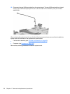
7. Remove the optical drive connector board (3). The optical drive connector board is available using
spare part number 432992-001.
94 Chapter 4 Removal and replacement procedures