


Diagnosing array problems 30
Diagnosing array problems
In this section
Controller board runtime LEDs.................................................................................................................. 30
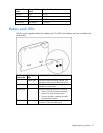
Battery pack LEDs................................................................................................................................... 31
Diagnostic tools ..................................................................................................................................... 32
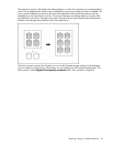
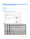
Controller board runtime LEDs
NOTE: During server power-up, each runtime LED illuminates randomly until POST has finished.
LED ID Color LED name and interpretation
1 Green
CR1: Idle Task LED. This LED, together with item 2, indicates the amount of
controller CPU activity. For details, see the following table.
2 Green
CR2: Gas Pedal LED. This LED, together with item 1, indicates the amount of
controller CPU activity. For details, see the following table.
3 Green
CR3: Heartbeat LED. This LED blinks every two seconds to indicate the controller
health.
4 Green
CR4: Command Outstanding LED. The controller is working on a command from
the host driver.
5 Green CR5: DMA Activity LED.
6 Green CR6: SAS Activity LED.
7 Amber
CR7: Drive Failure LED. A physical drive connected to the controller has failed.
Observe the Fault LED on each drive to determine which drive has failed.
8 Amber CR8: Controller Lockup LED.