


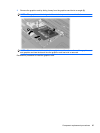
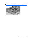
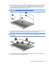
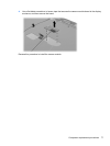

13. If it is necessary to replace the display bezel or display hinges, remove the six screw covers (1)
and six Torx T8M2.5×6.0 screws (2) that secure the display bezel to the display enclosure. The
display bezel is available using spare part number 494003-001 for models without a camera
module, 495030-001 for models with a camera module.
NOTE: See Display inverter or ambient light sensor on page 42 for display inverter replacement
instructions.
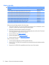
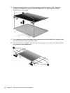
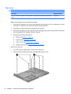
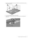
14. Flex the display bezel bottom edge (1), the inside edges of the left and right sides (2), and then the
display bezel top edge (3) until the bezel disengages from the display assembly.
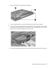
NOTE: There are two posts that protrude through two holes on the top edge of the bezel. So that
you do not break the posts, be sure to lift the bezel straight up when removing it from the display
assembly (4).
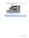
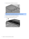
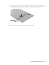
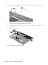
15. If it is necessary to remove the display panel, remove the two Torx T8M2.5×6.0 screws (1) that
secure the display panel to the display enclosure.
Component replacement procedures 73