


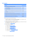
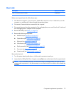
When replacing the system board, be sure that the following components are removed from the defective
system board and installed on the replacement system board:
●
Memory modules (see
Memory module on page 43)
●
WLAN module (see
WLAN module on page 45)
●
RTC battery (see
RTC battery on page 75)
●
Card reader board (see
Card reader board on page 77)
●
Heat sink (see
Heat sink on page 79)
●
Processor (see
Processor on page 81)
●
Power connector cable (see
Power connector cable on page 83)
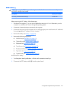
Remove the system board:
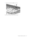
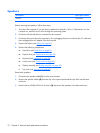
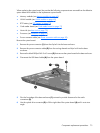
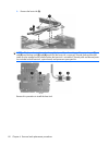
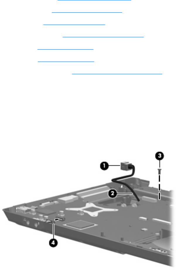
1. Remove the power connector (1) from the clip built into the base enclosure.
2. Remove the power connector cable (2) from the routing channel and clips built into the base
enclosure.
3. Remove the black Phillips PM2.5×4.0 screw (3) that secures the system board to the base enclosure.
4. Disconnect the USB board cable (4) from the system board.
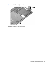
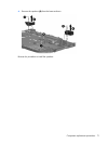
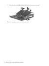
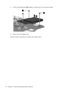
5. Flex the front edge of the base enclosure (1) outward to provide clearance for the audio
connectors (2).
6. Use the optical drive connector (3) to lift the right side of the system board (4) until it rests at an
angle.
Component replacement procedures 73