


130 Chapter4
field replaceable units
FRU removal and replacement
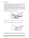
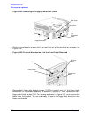
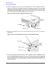
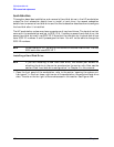
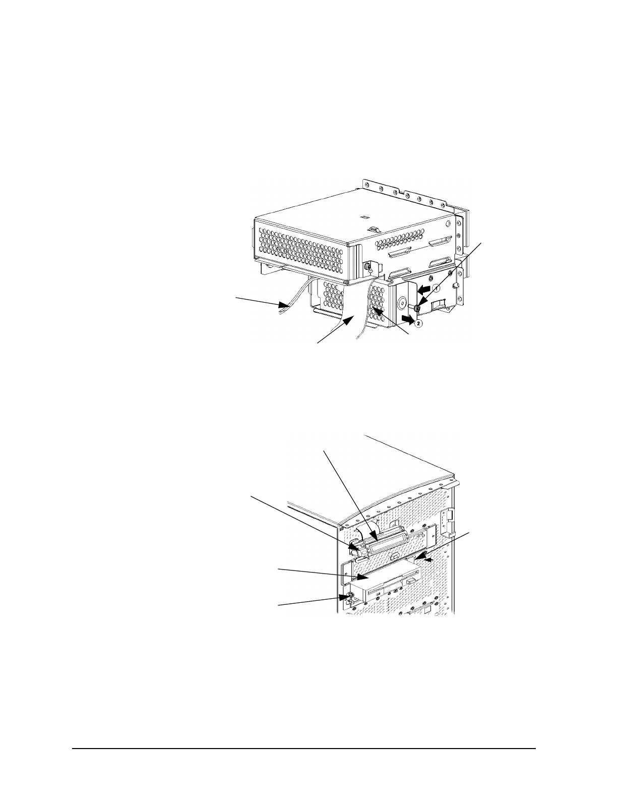
2. Remove the floppy rear disk cover by unscrewing the T-15 Torx screw as shown in
Figure 4-42. Note that the floppy’s rear cover is located on the rear of the removable
media chassis inside the system unit. Push the cover handle away from the rear of the
removable media chassis approximately one inch. Next pull the cover handle toward
you. Remove the data and power cables from their connectors.
Figure 4-42. Removing the Floppy Disk’s Rear Cover
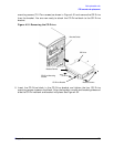
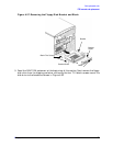
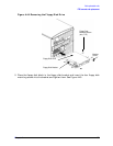
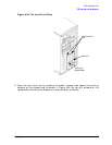
3. Rotate the workstation around until you can see the front of the unit as shown in
Figure 4-43..
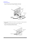
Figure 4-43. Front of Workstation with the Front Panel Removed
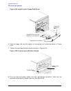
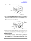
4. Remove both floppy disk bracket screws (T-15 torx screws) and pull the floppy disk drive
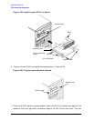
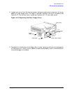
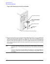
out of the chassis assembly as shown in Figure 4-43. Next remove the four floppy disk
mounting screws (T-10 torx screws) as shown in Figure 4-44 and remove the floppy disk
drive from the bracket. You are now ready to attach the floppy disk drive blank to the
floppy disk bracket.
T-15
Torx/slotted
Screw
Floppy Rear CoverData Cable
Power Cable
Bracket
Screw
(hidden)
LCD
Power Switch
Floppy Disk Drive
Bracket Screw