


Removal and Replacement Procedures
Maintenance and Service Guide 5–53
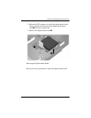
2. Turn the notebook upside down with the rear panel
toward
you.
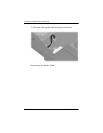
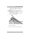
3. Disconnect the fan cable from the system board through
the
memory module compartment.
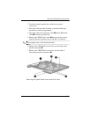
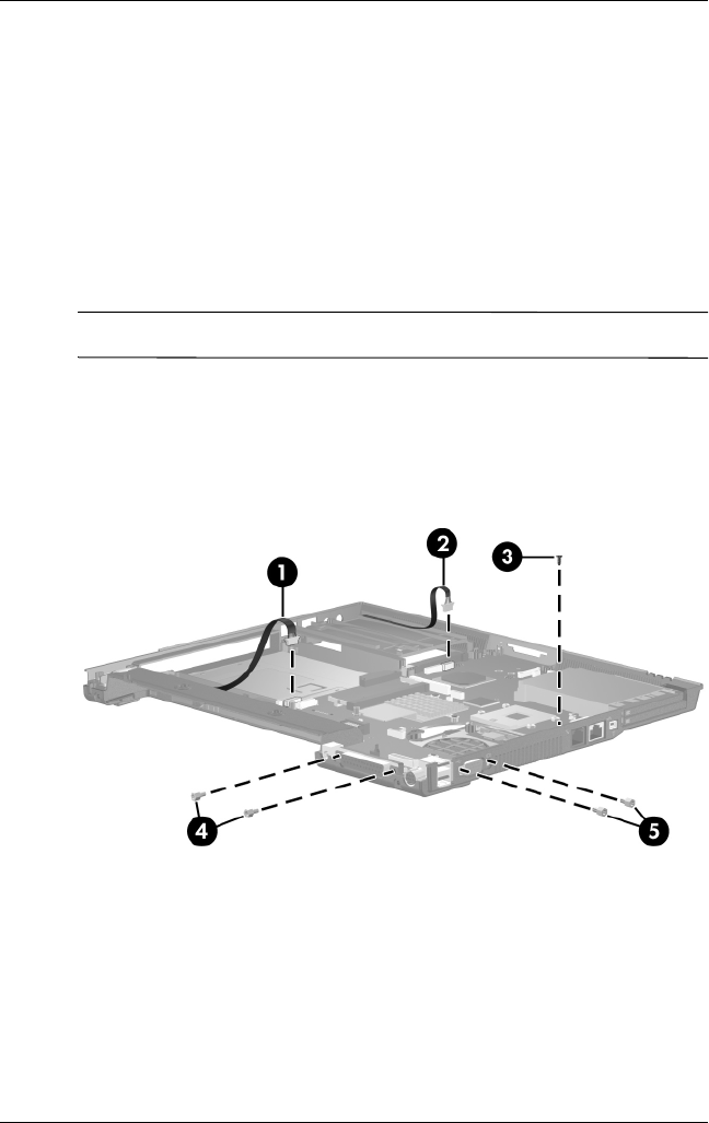
4. Disconnect the serial connector cable 1 and the Bluetooth
cable 2 from the system board.
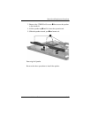
5. Remove the T8M2.0×4.0 screw 3 that secures the system
board to the base enclosure next to the RJ-11 connector.
✎
Step 6 applies only to full-featured models.
6. Remove the 2 HM5.0×9.0 screw locks on each side of the
parallel connector 4.
7. Remove the 2 HM5.0×9.0 screw locks on each side of
the
external monitor connectors 5.
Removing the System Board Screws and Screw Locks