


Index–6 Maintenance and Service Guide
Index
power/standby button 1–16
power/standby light
1–7
presentation mode button
1–17
processor
removal 5–31
spare part numbers 3–5,
3–21, 5–31
R
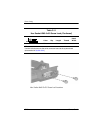
rear components 1–10
removal/replacement
preliminaries 4–1
procedures 5–1
right-side components 1–8
RJ-11 connector module and
cable
illustrated 3–13
removal 5–54
RJ-11 jack
location 1–11
pin assignments A–7
RJ-45 jack
location 1–11
pin assignments A–8
RTC battery
illustrated 3–12
removal 5–36
S
Screw Kit
contents C–1
spare part number 3–16,
C–1
screw listing C–1
security cable slot
1–13
serial connector module
removal 5–55
spare part number 3–7,
3–21, 5–55
serial connector module cable
3–13
serial number
3–1, 5–2
serial port
location 1–9
pin assignments A–3
service considerations 4–2
speaker
removal 5–45
spare part number 3–5,
3–22, 5–45
speakers, location 1–6
specifications
battery pack 6–8
CD-ROM drive 6–14
display 6–3, 6–4, 6–5
DVD/CD-RW Combo
Drive
6–10
DVD±RW and CD-RW
Combo Drive
6–12
DVD-ROM drive 6–9
hard drive 6–6
I/O addresses 6–19
interrupts 6–17
memory map 6–22
notebook 6–1
optical drive 6–9, 6–10,
6–12, 6–14
system DMA 6–16
static shielding materials 4–8