


5–4 Maintenance and Service Guide
Removal and Replacement Procedures
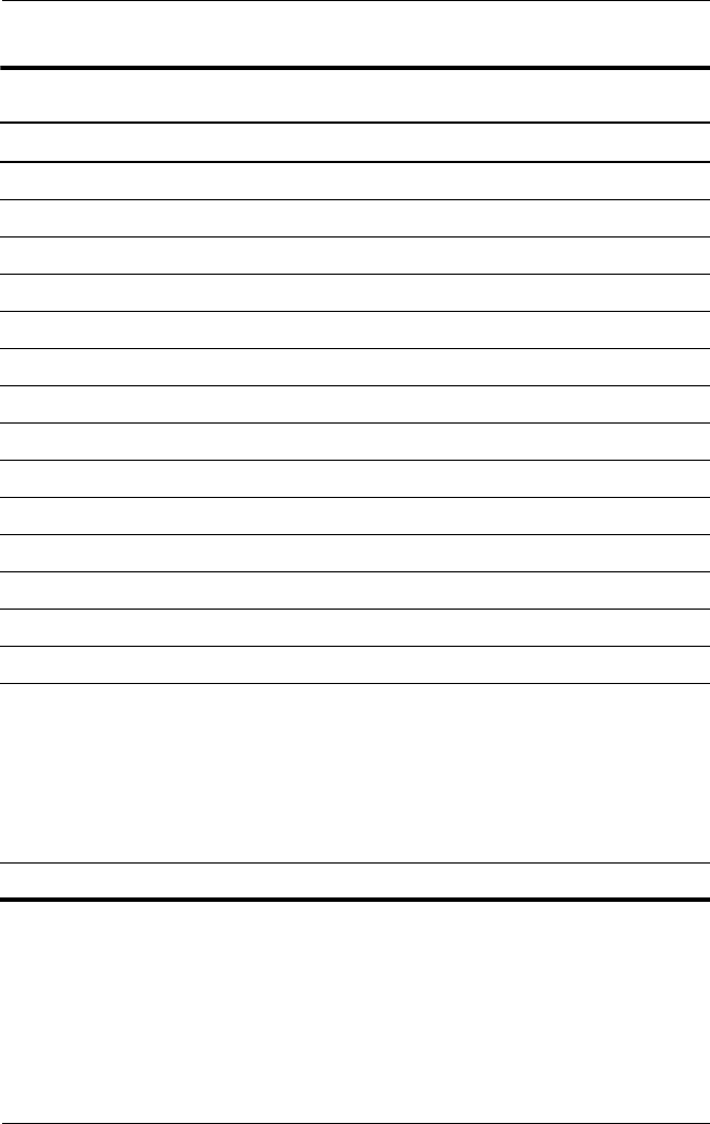
Section Description
# of Screws Removed
5.9 Keyboard 2
5.10 Switch cover 2
5.11 LED board 4
5.12 Fan 2 loosened
5.13 Heat sink 4 loosened
5.14 Processor 1 loosened
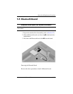
5.15 Modem board 2
5.16 Internal memory module 0
5.17 RTC battery 0
5.18 Display assembly 6
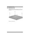
5.19 Top cover 15
5.20 Speaker 4
5.21 Digital media board 0
5.22 USB/audio board 1
5.23 System board 1 screw
4 screw locks on
HP
Compaq nc6110 and
nc6120 models
2 screw locks on
HP
Compaq nx6110 and
nx6120 models
5.24 Serial connector module 2 screw locks
Disassembly Sequence Chart
(Continued)