


Removal and Replacement Procedures
Maintenance and Service Guide 5–63
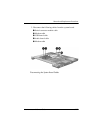
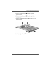
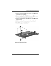
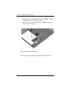
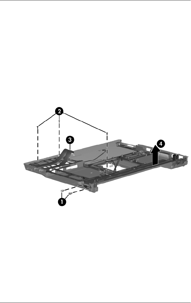
3. Remove the two Hex HM5.0×12.0 screw locks 1 on each
side of the serial connector.
4. Remove the three Torx8 T8M2.5×6.0 screws 2 that secure
the system board frame to the base enclosure.
5. Remove the audio board and USB board cables 3 from the
base enclosure.
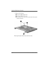
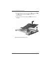
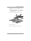
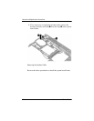
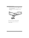
6. Lift the rear edge of the system board frame 4 until it
disengages from the base enclosure.
7. Remove the system board frame.
Remove the System Board Frame