


5–66 Maintenance and Service Guide
Removal and Replacement Procedures
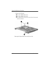
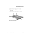
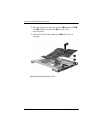
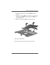
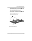
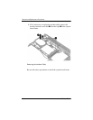
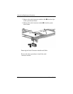
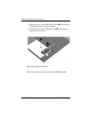
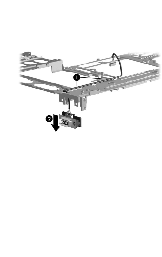
3. Remove the serial connector module cable 1 from the clips
in the system board frame.
4. Remove the serial connector module 2 from the system
board frame.
Removing the Serial Connector Module and Cable
Reverse the above procedure to install the serial
connector module.