


Connector Pin Assignments
Maintenance and Service Guide A–3
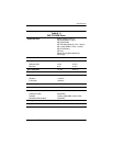
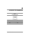
Table A-4
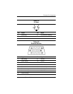
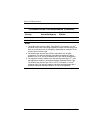
S-Video
Pin Signal Pin Signal
1 Ground (Y) 3 Y-Luminance (Intensity)
2 Ground (C) 4 C-Chrominance (Color)
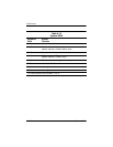
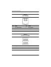
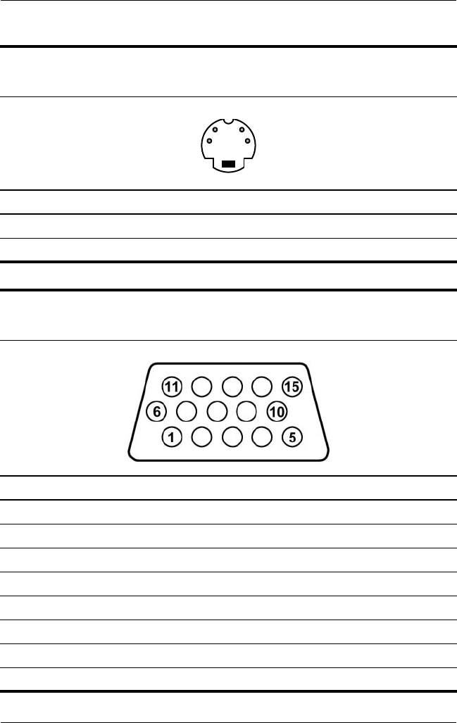
Table A-5
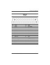
External Monitor
Pin Signal Pin Signal
1 Red analog 9 +5 VDC
2 Green analog 10 Ground
3 Blue analog 11 Monitor detect
4 Not connected 12 DDC 2B data
5 Ground 13 Horizontal sync
6 Ground analog 14 Vertical sync
7 Ground analog 15 DDC 2B clock
8 Ground analog
12
43