


Removal and Replacement Procedures
Maintenance and Service Guide 5–3
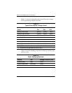
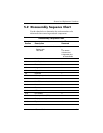
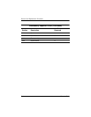
5.2 Disassembly Sequence Chart
Use the chart below to determine the section number to be
referenced when removing notebook components.
Disassembly Sequence Chart
Section Description
# of Screws
Removed
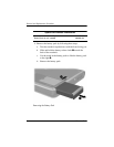
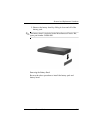
5.3 Preparing the notebook for disassembly
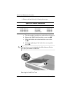
Battery pack
Hard drive
0
1 to remove
4 screws and
2 alignment pins
to disassemble
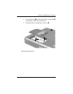
5.4 Notebook feet 0
5.5 MultiBay device 0
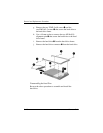
5.6 Bluetooth board 3
5.7 Integrated smart card 0
5.8 Optical drive 1
5.9 Keyboard 1
5.10 Memory expansion board 0
5.11 Modem board 2
5.12 Mini PCI communications board 2
5.13 Heat sink 5
5.14 Processor 0
5.15 LED switch cover 1
5.16 RTC battery 0
5.17 Security Module (TPM) 1
5.18 Display assembly 4
5.19 Top cover 18