


5–58 Maintenance and Service Guide
Removal and Replacement Procedures
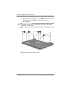
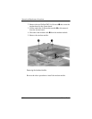
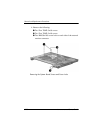
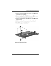
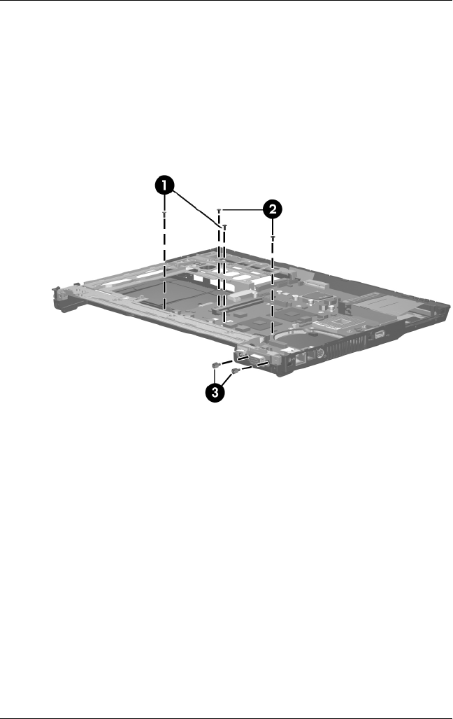
4. Remove the following:
1 Two Torx T8M2.5×6.0 screws
2 Two Torx T8M2.5×4.0 screws
3 Two HM5.0×10.0 screw locks on each side of the external
monitor connector
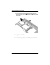
Removing the System Board Screws and Screw Locks