


5–4 Maintenance and Service Guide
Removal and Replacement Procedures
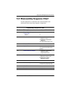
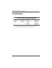
Section Description
# of Screws Removed
5.13 Internal Memory Module 0
5.14 RTC Battery 0
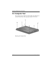
5.15 TouchPad 1
5.16 Mini Card Module 2
5.17 Switch Cover 3
5.18 Display Assembly 8
Å
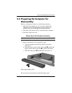
To prevent an unresponsive system and the display of a
warning message, install only a Mini Card device
authorized for use in your computer by the governmental
agency that regulates wireless devices in your country. If
you install a device and then receive a warning message,
remove the device to restore computer functionality. Then
contact Customer Care.
5.19 Top Cover 16 screws
5.20 Modem Module 2
5.21 System Board 4 screws
2 screw locks
5.22 System Board Frame 2 screw locks
3 screws
5.23 Serial Connector Module 0
5.26 USB/Audio Board 2
Disassembly Sequence Chart
(Continued)