


5–60 Maintenance and Service Guide
Removal and Replacement Procedures
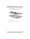
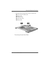
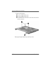
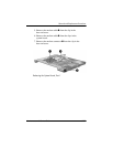
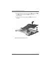
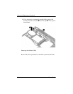
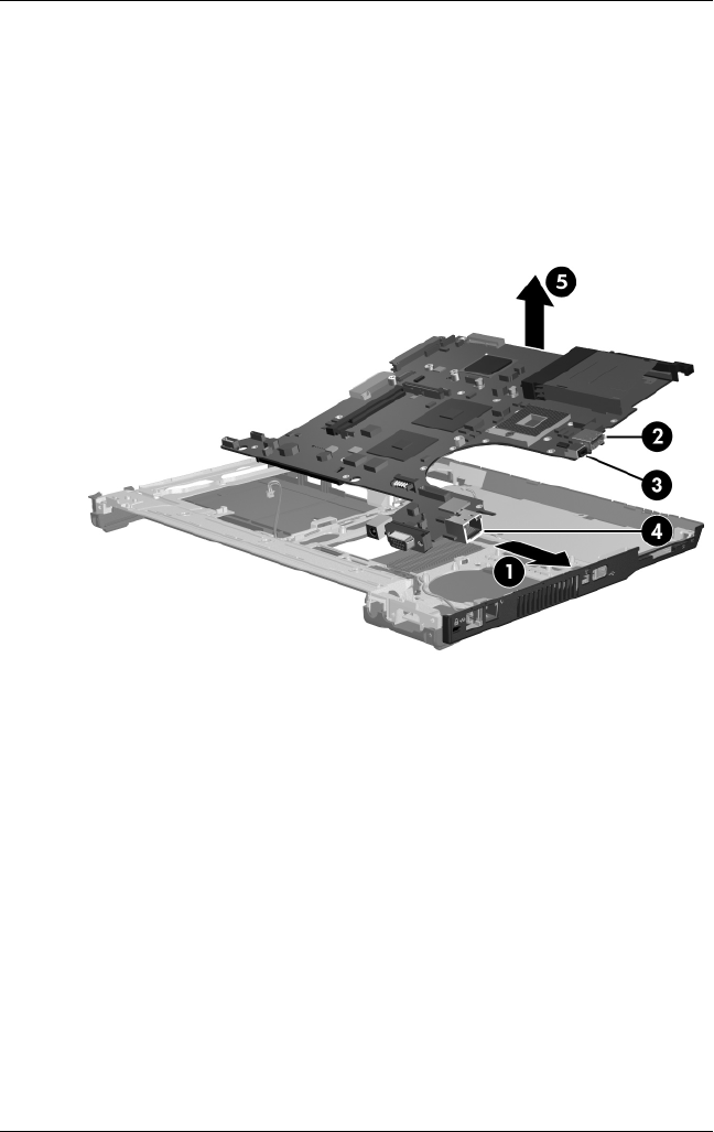
8. Flex the right side of the base enclosure 1 until the USB 2,
1394 3, and RJ-45 connectors 4 are clear of the
base enclosure.
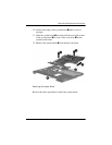
9. Lift the left side of the system board 5 until it rests at
an angle.
Releasing the System Board, Part 2