


Removal and Replacement Procedures
Maintenance and Service Guide 5–41
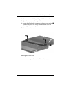
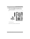
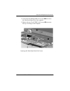
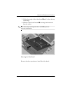
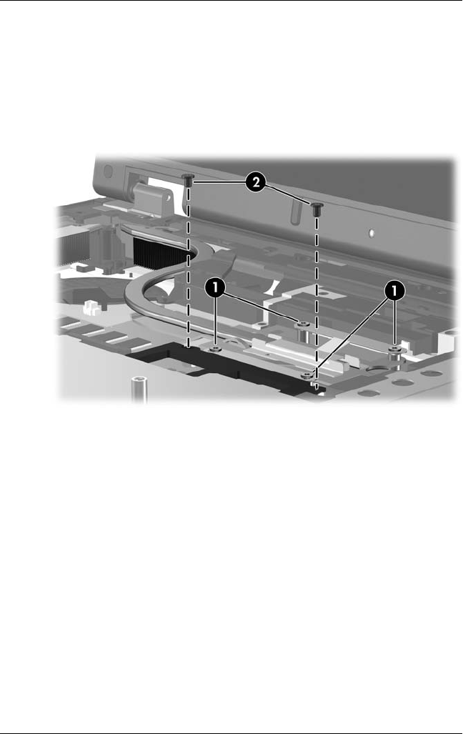
4. Loosen the four Phillips PM2.5×7.0 screws 1 that secure
the video board heat sink to the computer.
5. Remove the two Torx8 T8M2.5×4.0 screws 2 that secure
the top cover hinge to the computer.
Loosening the Video Board Heat Sink Screws