


5–52 Maintenance and Service Guide
Removal and Replacement Procedures
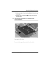
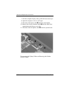
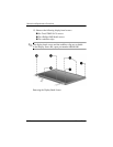
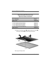
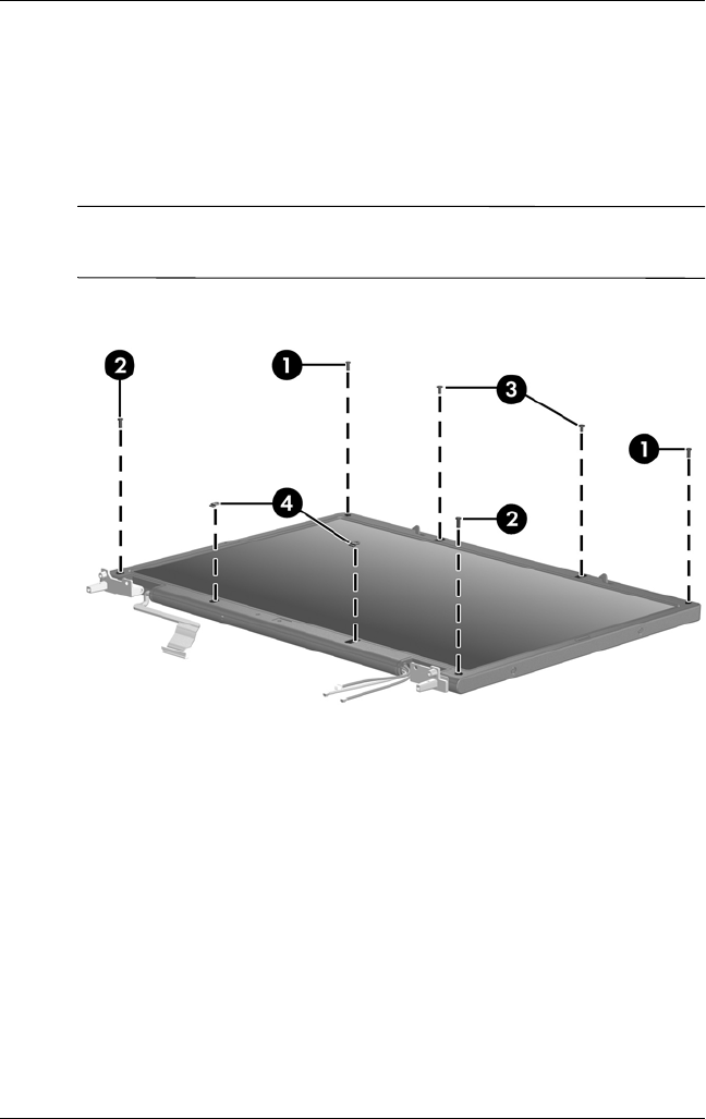
15. Remove the following display bezel screws:
1 Six Torx8 T8M2.5×7.0 screws
2 Two Phillips PM2.0×6.0 screws
3 Two stabilizer clips
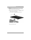
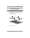
✎
The display bezel screws and the stabilizer clips are available
in the Display Screw Kit, spare part number 409940-001.
Removing the Display Bezel Screws