


1-5
Introducing the Switch
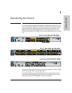
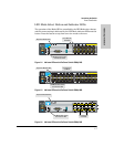
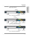
Front of the Switch
Introducing the Switch
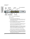
LEDs
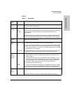
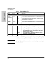
Table 1-1. Switch LEDs
Switch
LEDs
State Meaning
Power
(green)
On
Off
The switch is receiving power.
The switch is NOT receiving power.
Fault
(orange)
Off The normal state; indicates there are no fault conditions on the switch.
blink
orange*
A fault has occurred on the switch, one of the switch ports, module in the rear of the
switch, or the fan. The Status LED for the component with the fault will blink
simultaneously.
On On briefly after the switch is powered on or reset, at the beginning of switch self test.
If this LED is on for a prolonged time, the switch has encountered a fatal hardware
failure, or has failed its self test. See chapter 4, “Troubleshooting” for more information.
Locator
(Blue)
Reserved for future development
Test
(green)
Off The normal operational state; the switch is not undergoing self test.
On The switch self test and initialization are in progress after the switch has been power
cycled or reset. The switch is not operational until this LED goes off. The Self Test LED
also comes on briefly when you “hot swap” a mini-GBIC into the switch; the mini-GBIC
is self tested when it is hot swapped.
blink green* A component of the switch has failed its self test. The status LED for that component,
for example an RJ-45 port, and the switch Fault LED will blink simultaneously.
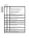
Port LEDs
(green –
Link and
Mode)
Link Indicates the port LEDs are displaying link information:
• if the port LED is on, the port is enabled and receiving a link indication from the
connected device.
• if the port LED is off, the port has no active network cable connected, or is not
receiving link beat or sufficient light. Otherwise, the port may have been disabled
through the switch console, the web browser interface, or ProCurve Manager.
if the port LED is blinking* (orange) simultaneously with the Fault LED, the
corresponding port has failed its self test.
Mode The operation of the Mode LED is controlled by the LED Mode select button, and the
current setting is indicated by the LED Mode indicator LEDs near the button. Press the
button to step from one view mode to the next. The default view is Activity (Act).
LED Mode
View
(green)
Act Indicates the port LEDs are displaying network activity information.
FDx Indicates port LEDs are lit for ports in Full Duplex Mode. Off indicates ½ duplex.