


2-3
Installing the Switch
Installation Procedures
Installing the Switch
Installation Procedures
Summary
1. Prepare the installation site (page 2-5). Ensure the physical environ-
ment is properly prepared, including having the correct network cabling
ready to connect to the switch and having an appropriate location for the
switch. See page 2-4 for some installation precautions.
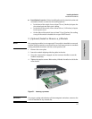
2. Install or remove a yl module (optional—page 2-7).
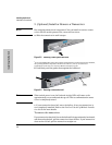
3. Install or remove a transceiver (optional—(page 2-8). If you have
installed a yl module, you can now install one or two transceivers.
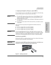
4. Install or remove mini-GBICs (optional—page 2-9). The switch has
four slots for installing mini-GBICs. Depending on where you will mount
the switch, it may be easier to install the mini-GBICs first. Mini-GBICs can
be installed or removed while the switch is powered on.
5. Verify the switch passes self test (page 2-11). Plug the switch into a
power source and observe that the LEDs on the switch’s front panel
indicate correct switch operation. When self test is complete, unplug the
switch.
6. Mount the switch (page 2-13). The Switch can be mounted in a 19-inch
telco rack, in an equipment cabinet, or on a horizontal surface.
7. Connect the switch to a power source (page 2-15). Once the switch is
mounted, plug it into the nearby main power source.
8. Connect the network cables (page 2-16). Using the appropriate
network cables, connect the network devices to the switch ports.
9. Connect a 620 RPS/EPS (optional—page 2-18). You may wish to use
a 620 RPS/EPS with your switch. To do so you must connect the external
power supply using the RPS or EPS cables supplied with the 620 RPS/EPS.
10. Connect a console to the switch (optional—page 2-22). You may wish
to modify the switch’s configuration, for example, to configure an IP
address so it can be managed using a web browser, from an SNMP network
management station, or through a Telnet session. Configuration changes
can be made easily by using the included console cable to connect a PC
to the switch’s console port.
At this point, the switch is fully installed. See the rest of this chapter if you
need more detailed information on any of these installation steps.