


2-19
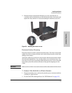
Installing the Switch
Installation Procedures
Installing the Switch
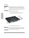
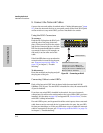
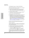
Operating Characteristics of the 620 RPS/EPS (J8696A)
The 620 RPS/EPS has two RPS ports, each of which can provide redundant
+12V power to a connected switch. If a switch with no AC power is connected
to an operating 620 RPS/EPS, it will not receive power. The switch must first
be powered on, then connected to the 620 RPS/EPS.
The 620 RPS/EPS also has two EPS Ports. The 620 RPS/EPS can provide a
maximum of 398 watts of PoE power to each of the two EPS ports. It is
important to understand the PoE power requirements of the 3500yl-PWR
Series switches because if the PoE power is not planned and implemented
correctly the end devices connected to the switch ports may not receive power
if an internal switch PoE power supply should fail. For further information
regarding the 620 RPS/EPS PoE capabilities, see the ProCurve Power over
Ethernet (PoE) for zl and yl Products Planning and Implementation Guide
and the ProCurve 620 Redundant and External Power Supply Installation
and Getting Started Guide, which is on the ProCurve Web site. See page 5-1
for details.
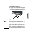
For redundant AC power, connect the 620 RPS/EPS to the switch using one
of the supplied RPS cables. For redundant or additional PoE power, connect
the 620 RPS/EPS to the switch using one of the supplied EPS cables. The RPS
and EPS cables are 2.00 meters (6.56 feet) in length. These cables are identical.
If accidentally cross connected, nothing will happen. No power will flow until
properly connected.
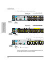
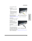
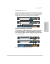
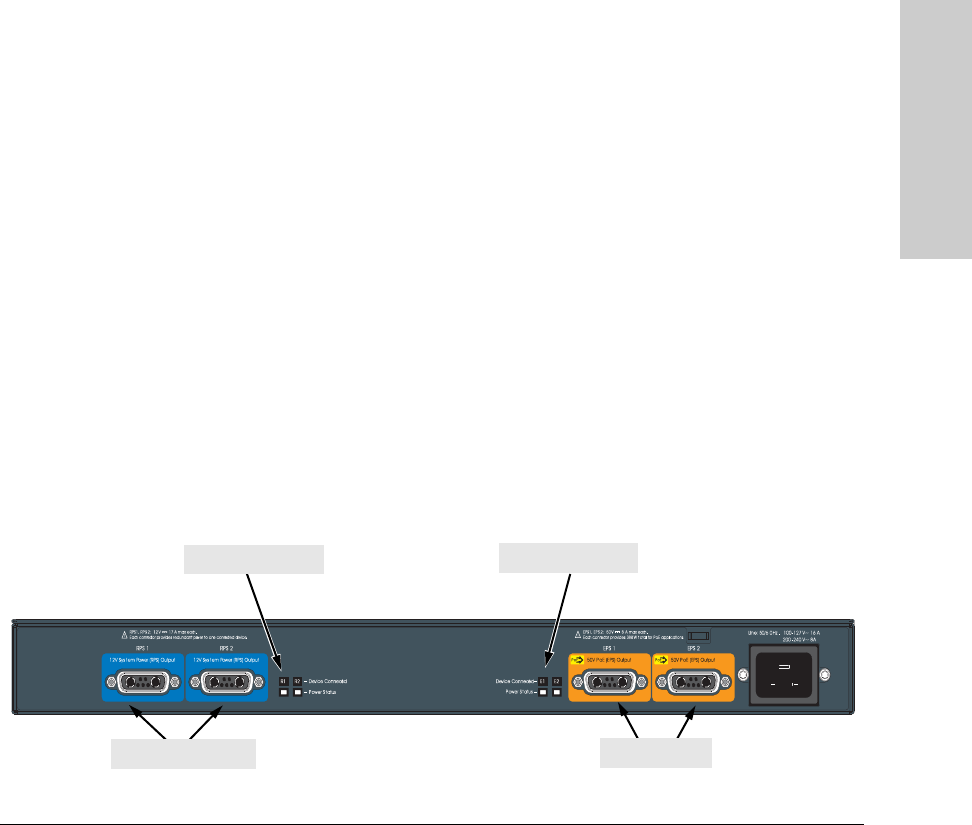
620 RPS/EPS LEDs
The 620 RPS/EPS LEDs are duplicated on the front and back of the device.
The following graphic shows an example of the back of the 620 EPS/RPS.
There are two dual colored (green/orange) LEDs for each RPS and EPS port:
■ Device Connected
■ Power Status
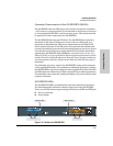
Figure 2-12. The back of a 620 RPS/EPS.
RPS ports
EPS ports
RPS port LEDs
EPS port LEDs