


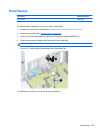
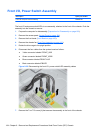
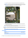
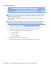
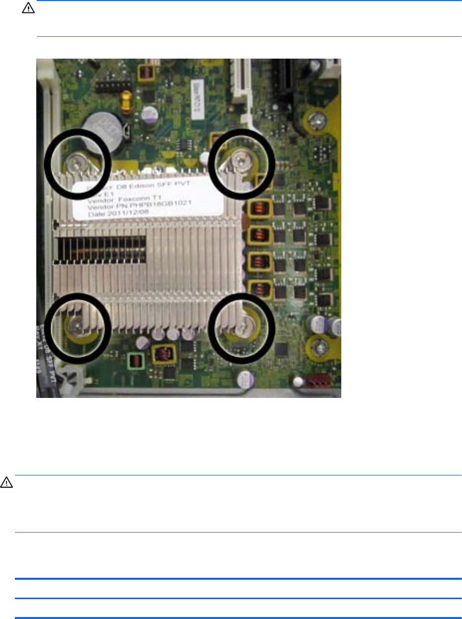
5. Loosen the four captive Torx T15 screws that secure the heat sink to the system board tray.
CAUTION: Remove heat sink retaining screws in diagonally opposite pairs (as in an X) to even
the downward forces on the processor. This is especially important as the pins on the socket are
very fragile and any damage to them may require replacing the system board.
Figure 8-35 Removing the heat sink
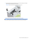
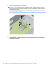
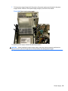
6. Lift the heat sink from atop the processor, and set it on its side to keep from contaminating the
work area with thermal grease.
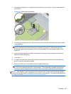
When reinstalling the heat sink, make sure that its bottom has been cleaned with an alcohol wipe and
fresh thermal grease has been applied to the top of the processor.
CAUTION: Heat sink retaining screws should be tightened in diagonally opposite pairs (as in an X)
to evenly seat the heat sink on the processor to avoid damage that could require replacing the system
board.
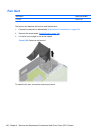
Failure to install the fan duct may cause the computer to overheat.
Processor
Description Spare part number
Intel Core i7 processor
198 Chapter 8 Removal and Replacement Procedures Small Form Factor (SFF) Chassis