


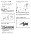
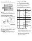

Connecting the ERM to the UPS
NOTE: To install a second ERM, plug the cable from
the second ERM into the socket at the rear of the first
ERM. Up to two ERM units can be connected.
Switching on the ERM circuit breaker
Charging the ERM batteries
Connect the UPS to a grounded utility power outlet. When the
UPS is plugged in, it automatically enters Standby mode and
begins charging the ERM batteries. With the UPS in Standby
mode, allow the ERM batteries to charge for at least 24 hours
before putting the UPS into service.
CAUTION: To ensure maximum runtime, be sure to
configure the UPS for the number of installed ERMs
using the UPS front panel controls.
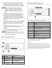
Configuring the UPS
After the ERMs are installed, place the UPS in Configure
mode, and use the UPS front panel controls and LED
indicators to configure the UPS for the number of attached
ERMs. Other UPS parameters that can also be configured
are the nominal utility voltage level and Site Wiring
Fault detection.
In Configure mode, the LED front panel display changes
function to enable modification of the UPS parameters. Each
LED is associated with a different parameter.
Available
settings
Parameter
Associated
LED
Explanation (when LED is
illuminated)
Nominal
Voltage
Setting
200/208
Nom
General
Alarm
(red)
Nominal utility voltage
level is set to 200/208
VAC (factory default for
326529-D71)
220 Nom
On
Battery
(red)
Nominal utility voltage
level is set to 220 VAC
230 Nom
Battery
Fault (red)
Nominal utility voltage
level is set to 230 VAC
(factory default for
326529-B31)
240 Nom
Site
Wiring
Fault (red)
Nominal utility voltage
level is set to 240 VAC
Wiring
Fault
Setting
Wiring Fault
Utility
(green)
Audible alarm sounds
when ground is missing or
line and neutral
connections are reversed
ERM
Setting
0 ERMs
0% to
25% load
(green)
UPS is configured for no
attached ERMs (factory
default)
1 ERM
26% to
50% load
(green)
UPS is configured for 1
attached ERM
2 ERMs
51% to
75% load
(green)
UPS is configured for 2
attached ERMs
To change the UPS configuration parameters:
1. Place the UPS in Configure mode.
The LEDs associated with the currently configured
parameters illuminate. A flashing green cursor indicates
where you are in the configuration process as you scroll
through the available settings.
2. To change the nominal voltage, press the On button to
advance the cursor to the LED associated with the
appropriate nominal voltage parameter. The selected
voltage configuration LED flashes.