


RTR Terminology
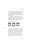
Figure 1–4 Facility Symbol
VM-0822A-AI
A facility name is mapped to specific physical nodes and their
roles using the CREATE FACILITY command.
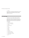
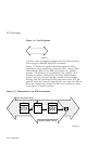
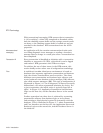
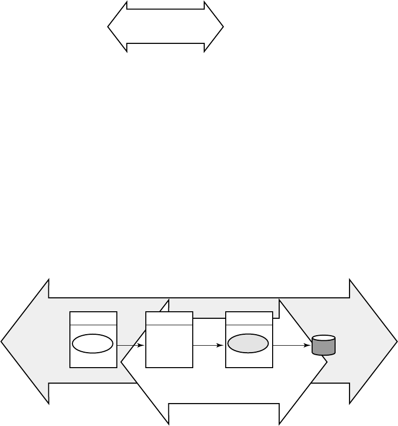
Figure 1–5 shows the logical relationship between client
application, server application, frontends (FEs), routers (TRs),
and backends (BEs) in the RTR environment at a specific
location. The database is represented by the cylinder. Two
facilities are shown (indicated by the large double-headed
arrows), the User Accounts Facility and the General Ledger
Facility. The User Accounts Facility uses three nodes, FE, TR,
and BE, while the General Ledger Facility uses only two, TR and
BE in the configuration shown. Its FEs are on nodes not shown
in the figure, at another location.
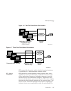
Figure 1–5 Components in the RTR Environment
FE TR BE
User Accounts Facility
Server
application
General Ledger Facility
VM-0823A-AI
Client
application
1–8 Introduction