


19
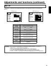
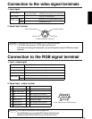
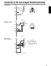
Connection to the video signal terminals
1.Input signal
S-VIDEO signal
VIDEO signal
AUDIO signal
Input
Output
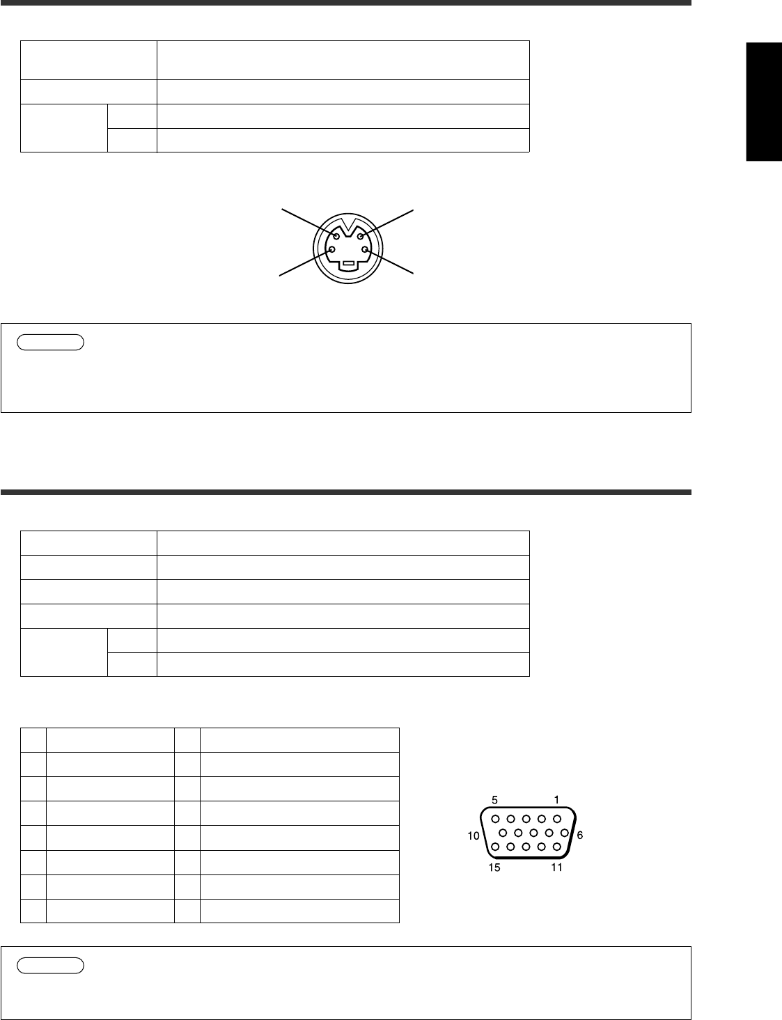
2.Signal input terminal
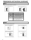
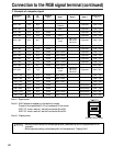
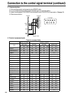
Connection to the RGB signal terminal
1.Input / output signal
Video signal
Horizontal sync signal
Vertical sync signal
Composite sync signal
Audio signal
Input
Output
Analog 0.7Vp-p 75 Ω termination (Positive polarity)
TTL level (Positive/negative polarity)
TTL level (Positive/negative polarity)
TTL level
200mVrms, 20k Ω below (MAX 3.0Vp-p)
0 ∼ 200mVrms, 1k Ω
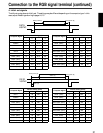
2.Signal input / output terminal
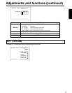
1
2
3
4
5
6
7
8
Video signal (Red)
Video signal (Green)
Video signal (Blue)
N.C
N.C
Ground (for R)
Ground (for G)
Ground (for B)
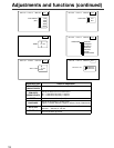
Luminance signal 1.0Vp-p, 75 Ω termination
Chrominance signal 0.286Vp-p (burst signal), 75 Ω termination
1.0Vp-p, 75 Ω termination
200mVrms, 20 kΩ below (MAX 3.0Vp-p)
0~200mVrms, 1k Ω
9
10
11
12
13
14
15
N.C
Ground
N.C
DDC (Display Data Channel)
Horizontal/Composite sync signal
Vertical sync signal
DDC (Display Data Channel)
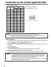
Caution
Video input signal terminals have priority in the following order.
1 S-VIDEO input terminal 2 RCA jack input terminal
Even when the video signal is displayed, only an audio signal is output to RGB audio output
terminals.
Chrominance signal
Ground
S VIDEO input (Mini DIN4 pin)
Luminance signal
Ground
D-sub 15pin shrink terminal (Female)
Caution
Do not use RGB cable other than that specified.
Some RGB cable may not operate DDC (Disply Data Channel)
because there are not connect from pin No. & to pin No.#.